6 Optional functions
RAS-(4-6)H(V)(R/N)(C/P)2E
SMGB0136 rev.0 - 07/2021
129
6
6.2.2.4 External output function setting
The following signals can be received by the outdoor unit PCB.
Specication for the main component requirements:
Components Specications
Auxiliary relay (*) High power relay, LY2F DC12V
? NOTE
(*)Donotusetherelaysmadewithdiodes.
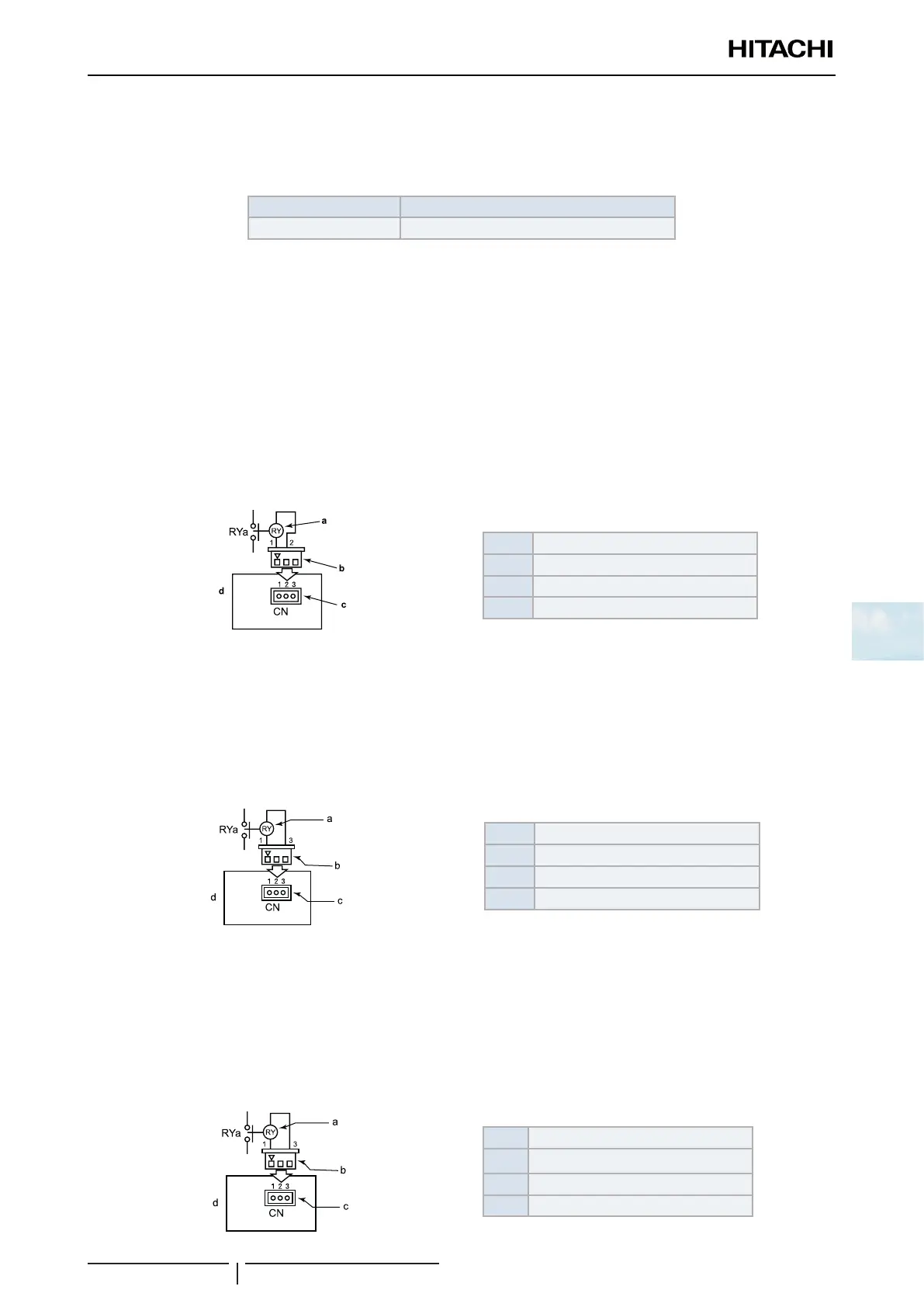
Operation signal (Control function nº1)
This function is used to receive the operation signal.
The auxiliary contact relay (RYa) is closed during the operation. The operation signal is sent to output terminals when
the indoor units (or a single indoor unit) are operating. This function can be used for the circulation or humidication
operation.
Setting example:
Operation Signal at Output 1 (between 1 and 2 pins of CN7).
7
a Auxiliary relay
b 3-pin connector
c Connector CN7
d Outdoor unit PCB1
Alarm signal (Control function nº2)
This function is used to receive the alarm signal.
The auxiliary contact relay (RYa) is closed when the alarm occurs. The alarm signal will be sent to output terminals when
the indoor units (or a single indoor unit) are operating and an alarm occurs in the system.
Setting example:
Alarm Signal at Output 2 (between 1 and 3 pins of CN7).
7
a Auxiliary relay
b 3-pin connector
c Connector CN7
d Outdoor unit PCB1
Compressor ON signal (Control function nº3)
This function is used to receive the compressor operation signal.
The auxiliary contact relay (RYa) is closed during the compressor operation. Compressor ON signal at output 2 (between
1 and 3 pins of CN7).
Setting example:
Compressor ON Signal at Output 2 (between 1 and 3 pins of CN7).
7
a Auxiliary relay
b 3-pin connector
c Connector CN7
d Outdoor unit PCB1