10 Troubleshooting
Troubleshooting in check mode
SMGB0136 rev.0 - 07/2021
301
10
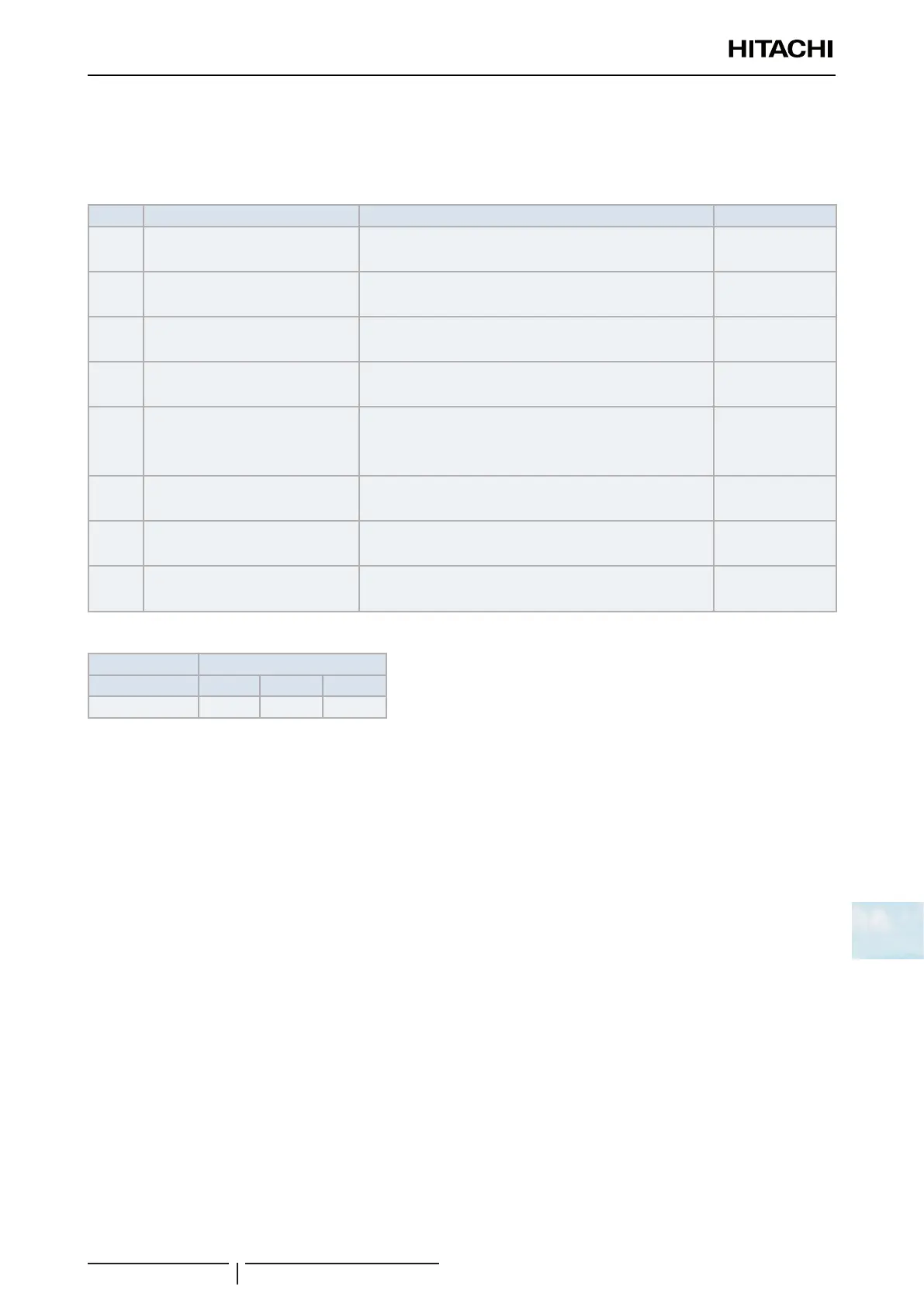
Activating condition of protection control code
To monitor the conditions such as the temperature change and others, the control of the frequency and other controls are
performed by the protection control in order to prevent the abnormal operations. The activating conditions of protection
control are shown in the table below:
Code Protection Control Activating Condition Remarks
P0
Low-Pressure Ratio Control at
Cooling Operation
IfCompressionRatioεexceedsathresholdvalue
=> Frequency Increase
—
P1
High-Pressure Ratio Control at
Heating Operation
IfCompressionRatioεislowerthanathresholdvalue
=> Frequency Decrease
—
P2
High-Pressure Increase Protection
High Pressure Switch for Control is activated
=> Frequency Decrease
—
P3
Over Current Protection
Inverter Output Current > (*1)A
=> Frequency Decrease
—
P4
Inverter Temperature Increase
Protection
Inverter Fin Temperature
RAS-3HVRC2≥70ºC
=> Frequency Decrease
—
P5
Discharge Gas Temperature
Increase Protection
Temperature at the top of compressor is high
=> Frequency Decrease
—
P9
Unbalance Power Source Detecting
Inverter Output Current exceeds a threshold value
=> Frequency Decrease
—
PA
Current Demand Control
Inverter Output Current exceeds a threshold value
=> Frequency Decrease
In case of Demand
Control Setting
(1*)
Connection 220-240V
HP 2 2.5 3
Current (A) 10.5 10.5 10.5
10.3.2 RAS-(4-6)H(V)(R/N)(C/P)2E
10.3.2.1 Troubleshooting by using the 7-segment display
? NOTE
Only the authorized person can carry out checks using this method.
The operating conditions and each part of the refrigerant cycle can be checked with the 7-segment display and push
switches on the PCB1 (models RAS-(4-6)HV(R/N)(C/P)2E and PCB2 (models RAS-(4-6)H(R/N)(C/P)2E) in the outdoor
unit.
Before carrying out checks
1 Turn ON the main power supply switch. Wait more than 20 seconds before starting the checks.
2 Check items:
- Information of the outdoor unit.
- Information of the indoor unit and ombined indoor units number.
- Expansion valve opening.
- Temperature at each part, etc.
- Information of the cause of the alarm code.
- Alarm code historical information.
3 Check the location of the 7-segment display and the push switches.
! DANGER
AC220-240V is applied to the PCB and electrical parts. Never touch the electrical parts and the cables when carrying out the
checks.