8 Electrical checks of main parts
Inverter
SMGB0136 rev.0 - 07/2021
156
8.1 Inverter
8.1.1 RAS-(4-6)HV(R/N)(C/P)2E
107
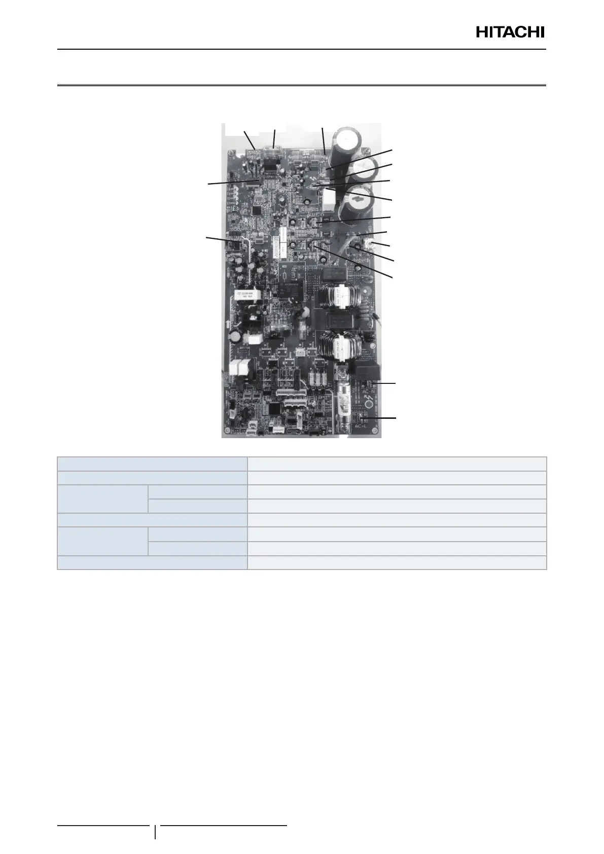
(3) Inverter Part of Outdoor Unit PCB
●
Detail of Check Points
AC-N
AC-L
L-COM
L1
L2
U
V
W
FU3
PCN30
PCN8
CN42
N
P
AC-L1
LED5
●
Check whether the high voltage still exists in the inverter PCB after power is disconnected. When the unit
is operated, LED5 is turned ON. At the time of powering off the unit, LED5 is turned OFF. In this case, the
residual voltage is less than DC50V.
●
If LED5 is turned ON while powering off the unit, please wait for about ve minutes, LED5 will turn OFF.
CAUTION
!
TROUBLESHOOTING
Applicable power source 1~ 230V 50Hz
Maximum output voltage 415V (Depends on power source voltage)
Maximum output
current
Compressor 20A
Fan controller 1.3A
Control method Vector control PWM (Pulse width modulator)
Output frequency
range
Compressor 11Hz to 130Hz
Fan controller 0 to 21.7rps
Frequency accuracy 0.01 Hz
1 Check whether the high voltage still exists in the inverter PCB after power is disconnected. When the unit is operated,
LED5 is turned ON. At the time of powering off the unit, LED5 is turned OFF. In this case, the residual voltage is less
than DC50V.
2 If LED5 is turned ON while powering off the unit, please wait for about ve minutes, LED5 will turn OFF.