User manual C4 – C6
66
6.7.9. Explanation of display during lifting.
While working with the crane, if the crane is set to crane operation, the following information is
shown on the remote control display. The values that appear on the display are explained below.
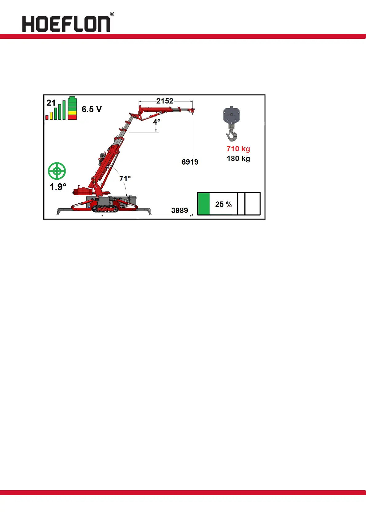
Figure: 85
The transmission frequency is shown at the top left. See figure 85; here it is set to 21.
The signal strength is indicated by 5 vertical bars. If the strength is good, they are all shown,
as in figure 85. As the signal weakens, the green bars disappear first, then the yellow and
red ones.
The battery state of charge is shown in the battery symbol in the top-left corner of the
screen. When the battery is fully charged, 3 green blocks, 1 yellow and 1 red are shown, as
in figure 85. As the battery discharges, the blocks go out, one at a time.
The voltage is shown in volts. In figure 85 this is 6.5 V.
The degree of levelling of the machine is also shown. This is indicated by the green circles in
the middle. In figure 85 the crane is 1.9° out of level.
The position of the main mast is 71° in figure 85.
The position of the jib is 4° in figure 85.
The radius of the outreach is 3989 mm in figure 85.
The lifting height is 6919 mm in (figure 85).
The length of the jib is 2152 mm in figure 85.
You can lift in this position 710 kg.
There is 180 kg in the lifting hook.
The crane is loaded at 25% in figure 85.
As can be seen in figure 85, the ballast is extended. If the ballast is retracted, the indicator
moves, and if the ballast is removed from the crane, it is no longer shown on the display.