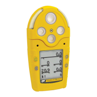
GasAlertMicro 5/PID/IR
User Manual
46
Applying Gas to the Sensors
The calibration cap, single gas calibration cap, and hose are shipped
with the detector. Refer to Figure 3.
and Table 11. for installation.
Note
The calibration cap and single gas calibration cap must only be
used during the calibration span process.
Figure 3. Applying Gas to the Sensors
Table 11. Applying Gas to the Sensors
Single Gas Calibration Cap
a Caution
If an O
3
or ClO
2
sensor is located in the Toxic 2 position
(refer to Figure 3.
and Table 11.), a single gas calibration
cap must be used to ensure accurate calibration.
To calibrate O
3
and ClO
2
sensors using the single gas calibration cap,
refer to Figure 4.
, Table 12., and complete the following procedures.
1. Insert the cap into the Toxic 2 sensor position on the detector
(refer to Figure 3.
). Press firmly until the release tabs click.
2. Connect the calibration hose to the gas cylinder and to the
intake inlet on the cap.
3. Proceed to Calibration Procedure
.
Item Description
1
Detector with calibration cap
2
Calibration hose
3
Regulator and gas cylinder
4
Toxic 2 sensor position
5
Single gas calibration cap
 Loading...