47
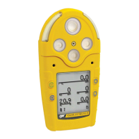
GasAlertMicro 5/PID/IR
Calibration and Setting Alarm Setpoints
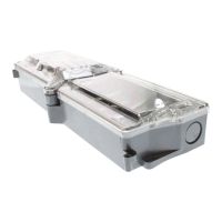
Table 12. Single Gas Calibration Cap
Figure 4. Single Gas Calibration Cap
Note
The arrow on the cap indicates the direction of gas flow from
intake to outtake.
Removing the Single Gas Calibration Cap
Using the thumb, push forward against both the inlet and the outlet
simultaneously to remove the cap from the detector.
Figure 5. Removing the Single Gas Calibration Cap
Calibration Procedure
To calibrate the detector and set the alarm setpoints, perform the
following procedure.
Note
To bypass a step during the calibration process (after auto
zero), press A.
Item Description
1
Intake inlet
2
Calibration hose
3
Gas flow direction arrow
4
Output outlet
 Loading...