EVS Series Manual — P/N LS10062-001SK-E:D 3/15/2022 11
Section 3: Installation
This section of the manual is intended to help you plan your tasks to complete the installation. Please read this section thoroughly, especially
if you are installing a EVS Series control panel for the first time.
3.1 Environmental Specifications
It is important to protect the EVS panel from water. To prevent water damage, the following precautions should be followed when installing
the units:
• Mount in indoor, dry environments only.
• Do not mount directly on exterior walls, especially masonry walls (condensation).
• Do not mount directly on exterior walls below grade (condensation).
• Protect from plumbing leaks.
• Protect from splash caused by sprinkler system inspection ports.
• Do not mount in areas with humidity-generating equipment (such as dryers, production machinery).
When selecting a location to mount the control panel, the unit should be mounted where it will NOT be exposed to temperatures outside the
range of 32°F-120°F (0°C-49°C) or humidity outside the range of 10%-93% at 86°F (30°C) non-condensing.
3.2 Wiring Specifications
Induced noise (transfer of electrical energy from one wire to another) can interfere with telephone communication or cause false alarms. To
avoid induced noise, follow these guidelines:
• Isolate input wiring from high current output and power wiring. Do not pull one multi-conductor cable for the entire panel. Instead,
separate the wiring as follows:
• Do not pull wires from different groups through the same conduit. If you must run them together, do so for as short a distance as
possible or use shielded cable. Connect the shield to earth ground at the panel. You must route high and low voltages separately.
• Ground fault and wire to wire short impedance to any terminal is 0Ω.
• Route the wiring around the inside perimeter of the cabinet. It should not cross the circuit board where it could induce noise into the
sensitive microelectronics or pick up unwanted RF noise from the high speed circuits. Refer to the FACP manual for wire routing
examples.
• High frequency noise, such as that produced by the inductive reactance of a speaker or bell, can also be reduced by running the wire
through ferrite shield beads or by wrapping it around a ferrite toroid.
3.3 Cabinet Mounting
Refer to the appropriate FACP manual for cabinet mounting instructions and wire routing examples. See Section 1.4 for a list of related doc-
umentation.
3.4 Electrical Specifications
High voltage Relay circuits
SLC loops AC power Terminals
Audio input/output Phone line circuits
Notification circuits NAC1 through NAC6
SBUS
NOTE: All circuits are power limited except the battery and AC cabling. Maintain 0.25 inch spacing between high and low voltage circuits and
between power-limited and non-power limited circuits.
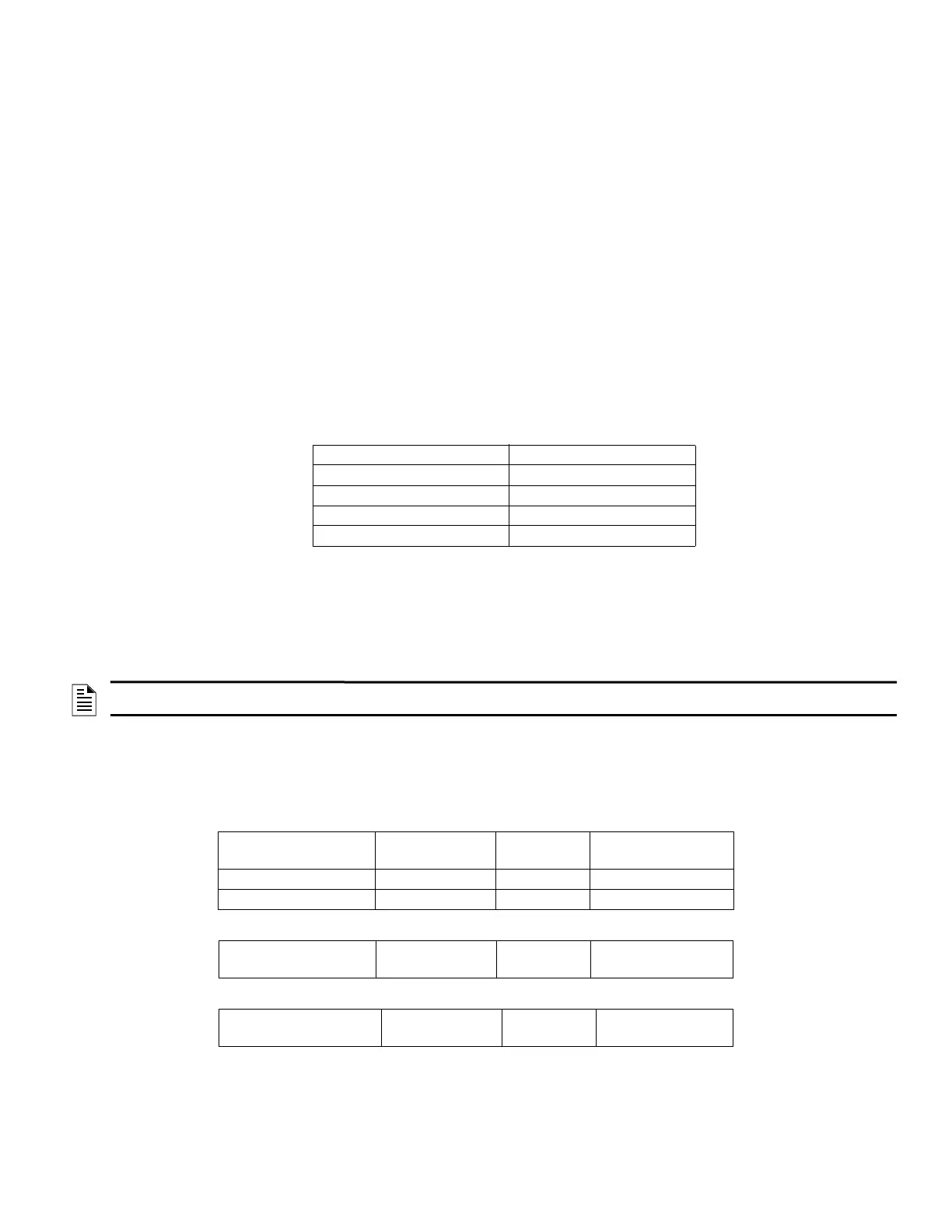
Module Voltage
Standby
Current
*Alarm Current
(fully loaded system)
EVS-50W 25V 120V 60 Hz 350 mA 1100 mA
EVS-50W 70V 120V 60 Hz 350 mA 1200 mA
Table 3.1 EVS-50W AC Current Draw
Module Voltage
Standby
Current
*Alarm Current
(fully loaded system)
Table 3.2 EVS-125W AC Current Draw
Module Voltage
Standby
Current
*Alarm Current
(fully loaded system)
Table 3.3 EVS-100W AC Current Draw

 Loading...


