EVS Series Manual — P/N LS10062-001SK-E:D 3/15/2022 15
Installing the EVS-VCM EVS Device Installation
4.2.4 Installing and Connecting the EVS-SW24 to the EVS-VCM
The EVS-SW24 adds 24 switches to the 5820XL-EVS and 6820EVS control panels for a total of 40 (with the 16 non-EVS switches on the
EVS-VCM).
Follow these steps to install and connect the EVS-SW24:
1. Open the cabinet door and dead front panel.
2. Remove AC power from the main control panel.
3. Disconnect the backup batteries.
4. Install the EVS-SW24 on the six mounting studs located on the inside of the dead front panel. See Figure 4.3 for mounting locations.
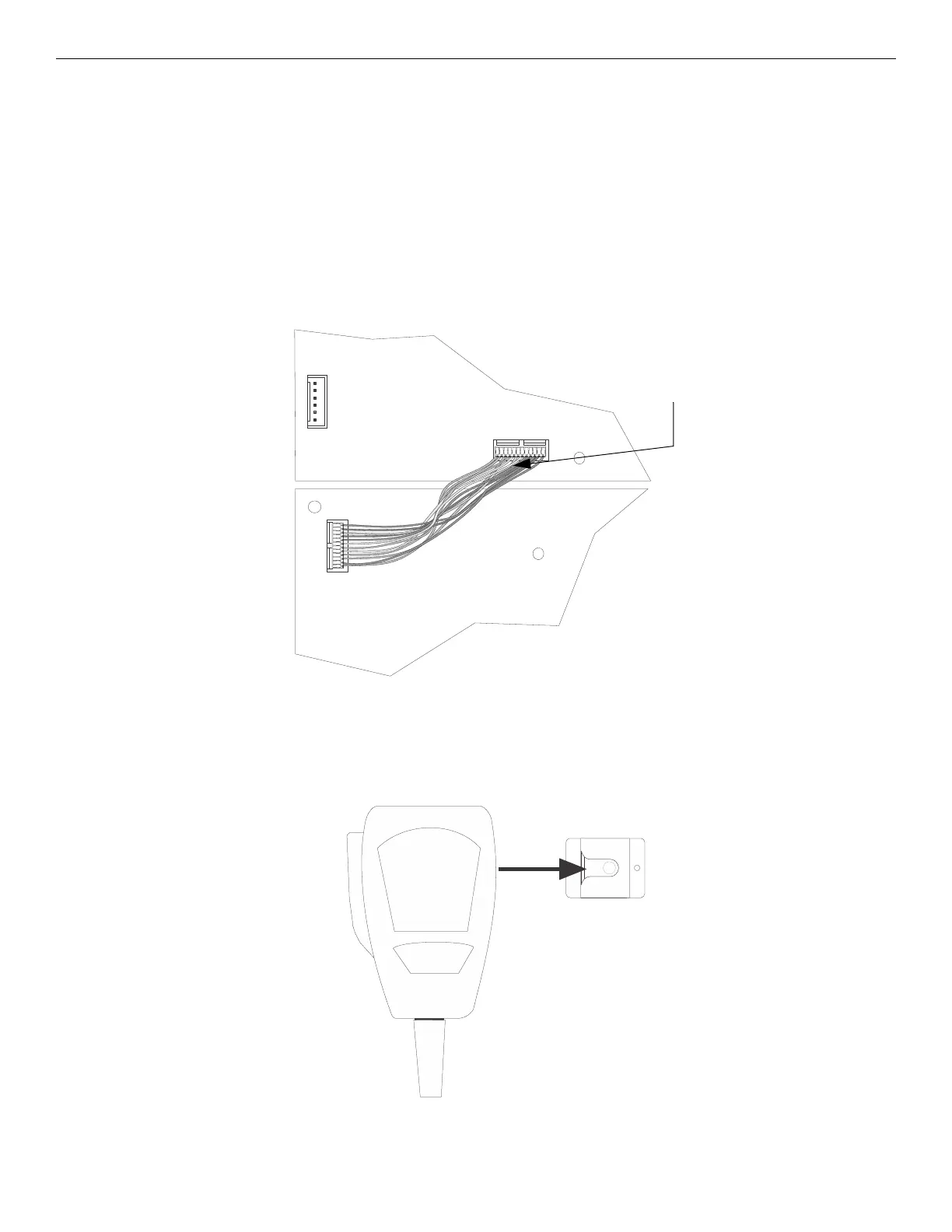
5. Connect one end of the wiring assembly (P/N 130398, supplied) to the EVS-VCM and the other end to the EVS-SW24 as shown in
Figure 4.5.
6. Secure the switch expander to the dead front panel using the supplied six ¼” hex nuts.
7. Restore AC power.
8. Reconnect backup batteries.
4.2.5 Installing the Microphone
To install the microphone follow these steps:
1. Clip the microphone into the microphone clip.
EVS-VCM
EVS-SW24
cable assembly
Figure 4.5 Connection for EVS-VCM to EVS-SW24
Figure 4.6 Sliding Microphone into Microphone Clip

 Loading...


