42 EVS Series Manual — P/N LS10062-001SK-E:D 3/15/2022
EVS Device Installation Installing the EVS-100WBU
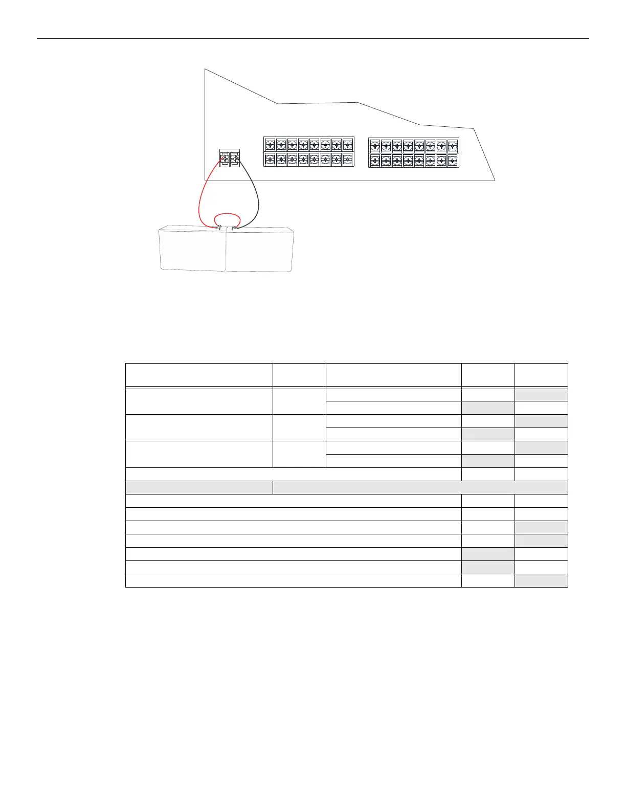
3. Connect the red wire from the battery harness to the positive (+) side of battery #1.
4.6.12 Calculating Current Draw and Standby Battery
This section helps determine the current draw and standby battery needs for your installation (18 AH maximum will fit in cabinet). Complete
the remaining instructions in Table 4.6.
Batteries larger than 18 AH will not fit in the main control cabinet, and must be housed in the RBB Accessory Battery Cabinet. The system
supports a maximum of 35 AH.
4.7 Installing the EVS-100WBU
The EVS-100WBU provides backup capability when operating the EVS-100W in the 100 watt with backup mode for both single and dual
channel setups. The EVS-100WBU mounts on the EVS-100W board on the standoffs provided.
Figure 4.46 Battery Connection to EVS-100W
Device
No. of
Devices
Current Per Device
Standby
Current
Alarm
Current
EVS-100W 25V 1 Standby: 110 mA 110 mA
Alarm: 1.2 A 1.2 A
EVS-100W 70.7V 1 Standby: 110 mA 110 mA
Alarm: 1.4 A 1.4A
EVS-100WBU 1 Standby: 40 mA 40 mA
Alarm: 110 mA 110 MA
A Current Subtotals: mA mA
Notification Devices Refer to device manual for number of devices and current ratings.
B Current Subtotals: mA mA
C Total current rating of all devices in system (Line B) X 0.001 A A
D Number of standby hours (24 or 60 for NFPA 72) H
E Multiply line C (standby current) and D: Total standby AH AH
F Alarm sounding period in hours (For example, 5 minutes = 0.0833 hours): H
G Multiply line C (alarm current) and F: Total alarm AH
AH
H Add lines E and G (AH = Ampere Hours): Total AH required AH
Table 4.6 Current Draw EVS-100W

 Loading...


