18 EVS Series Manual — P/N LS10062-001SK-E:D 3/15/2022
EVS Device Installation Installing the EVS-50W
5. Install remaining fasteners and tighten.
4.3.3 Mounting the EVS-50WBD Board Only
1. Ensure AC and DC power have been removed from the panel.
2. If this module is a replacement for an existing EVS-50W, remove the seven screws which secure the board to the enclosure.
3. Align the mounting holes over the PEM standoffs in the back of the cabinet.
4. Secure the board to the enclosure with the screws removed in step 2.
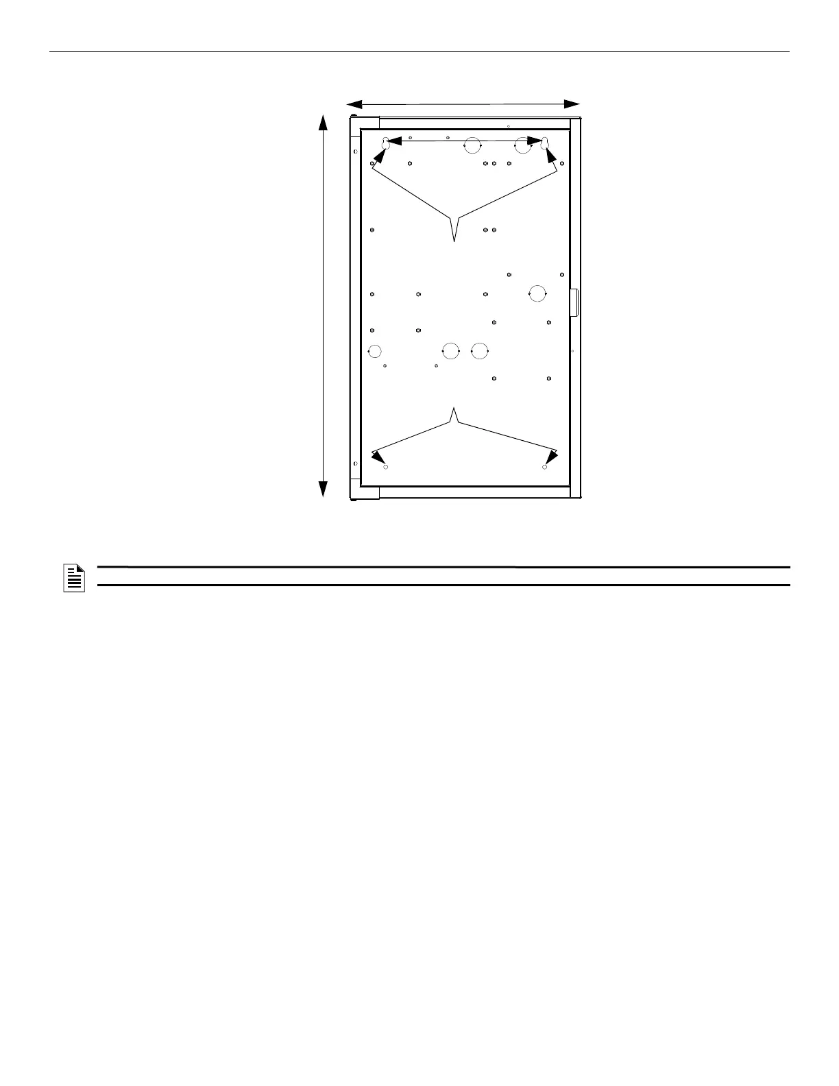
14.5”
11”
24.75”
bottom
mounting holes
mounting
key holes
Figure 4.10 Amplifier Cabinet Flush-Mount Dimensions and Mounting Hole Locations
NOTE: Installation and wiring of this device must be done in accordance with NFPA 72 and local ordinance

 Loading...


