34 EVS Series Manual — P/N LS10062-001SK-E:D 3/15/2022
EVS Device Installation Installing the EVS-100W
Batteries larger than 18 AH will not fit in the main control cabinet, and must be housed in the RBB Accessory Battery Cabinet. The system
supports a maximum of 35 AH batteries.
4.6 Installing the EVS-100W
This section provides information on how to install the EVS-100 for use with the 5820XL-EVS or 6820EVS.
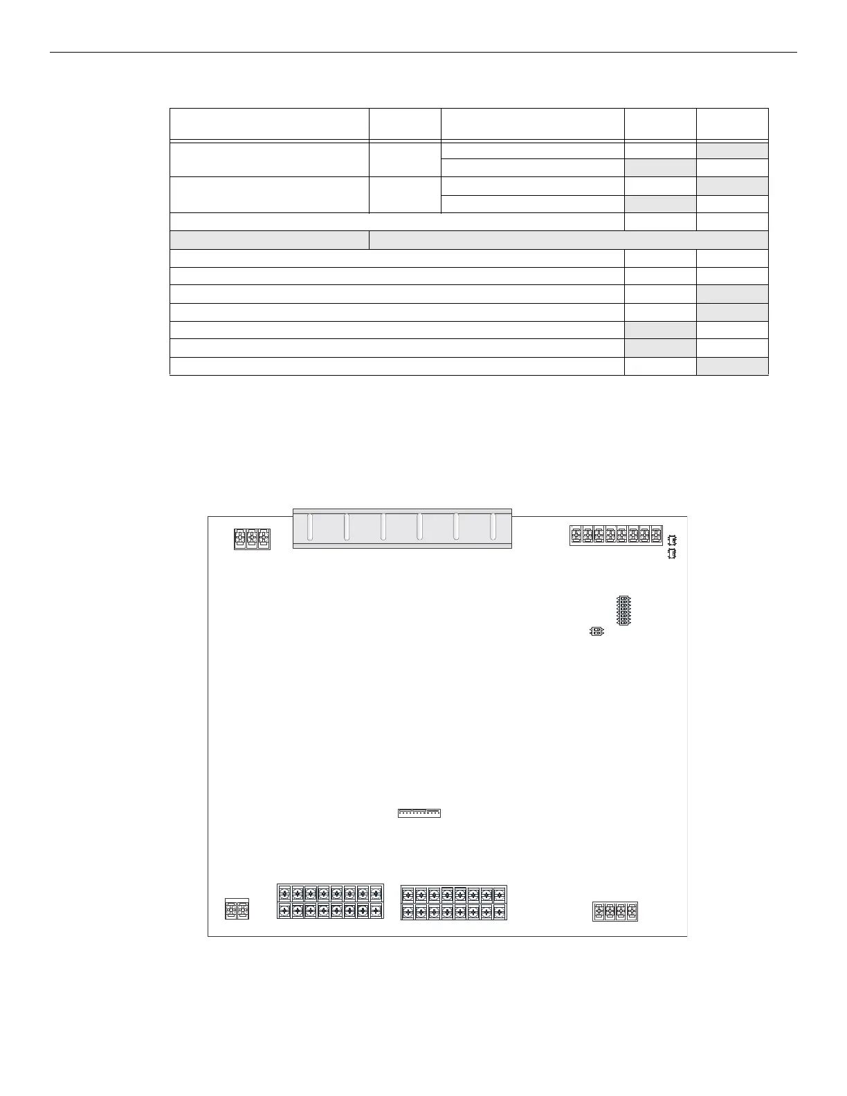
4.6.1 EVS-100W Board Layout
Figure 4.34 shows the location of terminals, DIP switches and expander connection used in the installation of the EVS-100W.
Device
No. of
Devices
Current Per Device
Standby
Current
Alarm
Current
EVS-125W 1 Standby: 375 mA 375mA
Alarm: 700 mA 700mA
EVS-CE4 0 or 1 Standby: 20 mA 20mA
Alarm (All Channels): 180 mA 180mA
A Current Subtotals: mA mA
Notification Devices Refer to device manual for number of devices and current ratings.
B Current Subtotals: mA mA
C Total current rating of all devices in system (Line B) X 0.001 A A
D Number of standby hours (24 or 60 for NFPA 72) H
E Multiply line C (standby current) and D: Total standby AH AH
F Alarm sounding period in hours (For example, 5 minutes = 0.0833 hours): H
G Multiply line C (alarm current) and F: Total alarm AH
AH
H Add lines E and G (AH = Ampere Hours): Total AH required AH
Table 4.4 Current Draw EVS-125W
AC connector
VBUS1 VBUS2
test switches
SBUS ID
DIP switch
amp mode
DIP switch
SBUS
audio circuits
battery
connector
Figure 4.34 Components Layout for EVS-100W
backup card connector

 Loading...


