40 EVS Series Manual — P/N LS10062-001SK-E:D 3/15/2022
EVS Device Installation Installing the EVS-100W
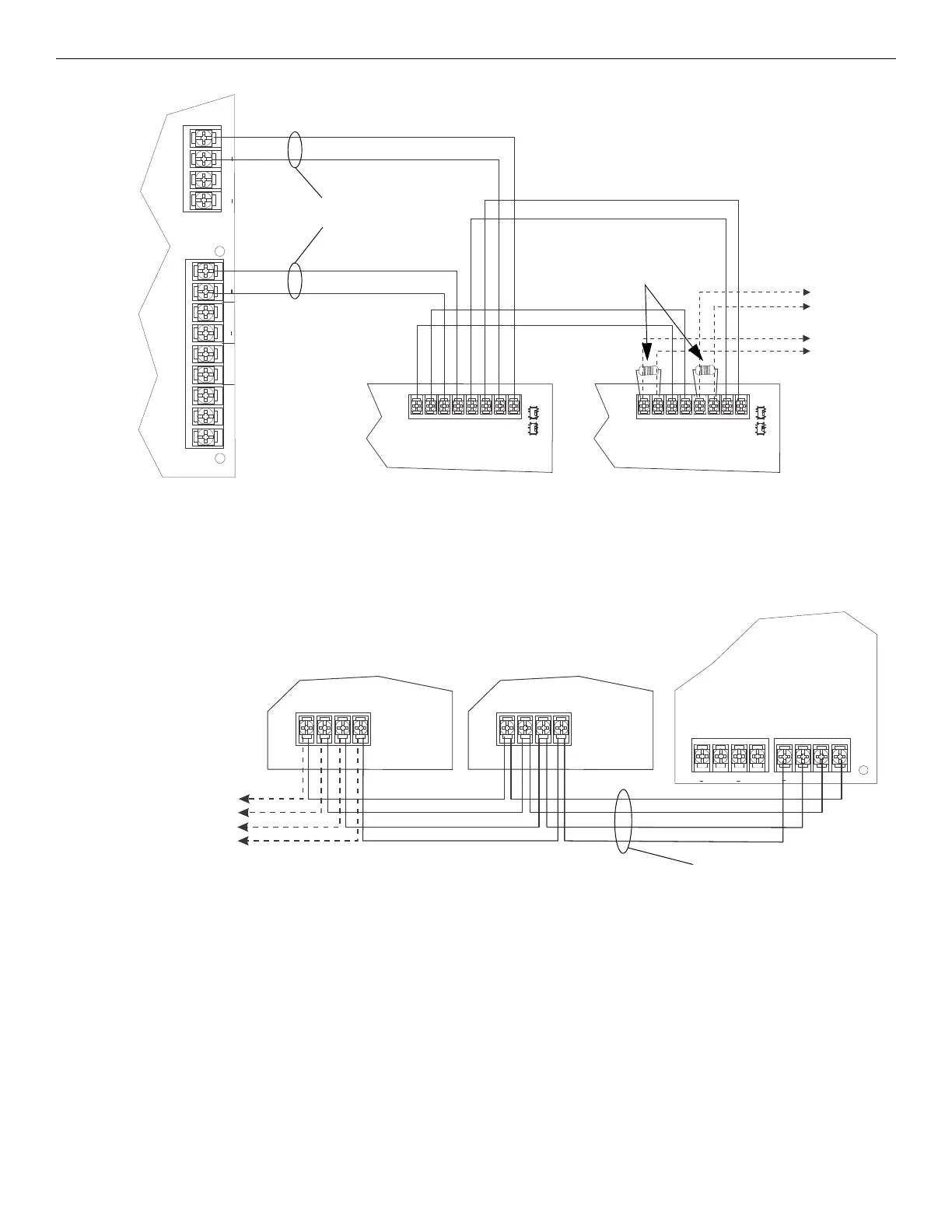
4.6.7 SBUS Wiring
This section contains information on how to connect up to four EVS-100W onto the main control SBUS. Refer to Section 4 of the FACP
Installation manual for SBUS specifications. Wire the SBUS to either the EVS-VCM or SBUS Out terminals on the FACP as shown in
Figure 4.43.
See Section 4.10 for information on setting SBUS addresses.
4.6.8 Setting the EVS-100W Backup Mode
When the EVS-100W is connected to a 5820XL-EVS version 13 or prior, see Figure 4.44 below to set the amplifier mode. If using version
14 or later, the mode is set using HFSS (Honeywell Fire Software Suite) and the DIP switch mode selector is ignored.
The amplifier modes are as follows:
• 50 Watt with backup - Amp A powers audio circuits 1 - 8. Amp A is backed up by onboard Amp B. (Default, DIP setting at position 2).
• 100 Watt with no backup - Amp A powers audio circuits 1 - 4. Amp B powers audio circuits 5 - 8. There is no backup.
(DIP setting at position 1).
• 100 Watt with backup (requires EVS-100WBU) - Amp A powers audio circuits 1 - 4. Amp B powers audio circuits 5 - 8. The EVS-
100WBU will back up Amp A or Amp B but never both. (DIP setting at position 3).
AUX
CMD2 CMD1
AUDIO
COMMON
IN
GND
VBUS 1 IN
VBUS 1 OUT
+
+
VBUS 2 IN
VBUS 2 OUT
+
+
Vout1-
Vout1+
Vin1-
Vin1+
Vout2-
Vout2+
Vin2-
Vin2+
EVS-100W
EVS-VCM
supervised,
power-limited
Class B
to next
EVS-100W
UL-listed 15kΩ
EOL at last device
on the VBUS
EVS-100W
Figure 4.42 VBUS2 Wiring for Dual Channel for EVS-VCM
supervised,
power-limited
Class B
EVS-VCM
or
SBUS (Out) on FACP
Figure 4.43 Connecting EVS-100W to the SBUS
to next
EVS-100W
(max 4)
EVS-100W
EVS-100W

 Loading...


