EVS Series Manual — P/N LS10062-001SK-E:D 3/15/2022 45
Installing the EVS-RVM EVS Device Installation
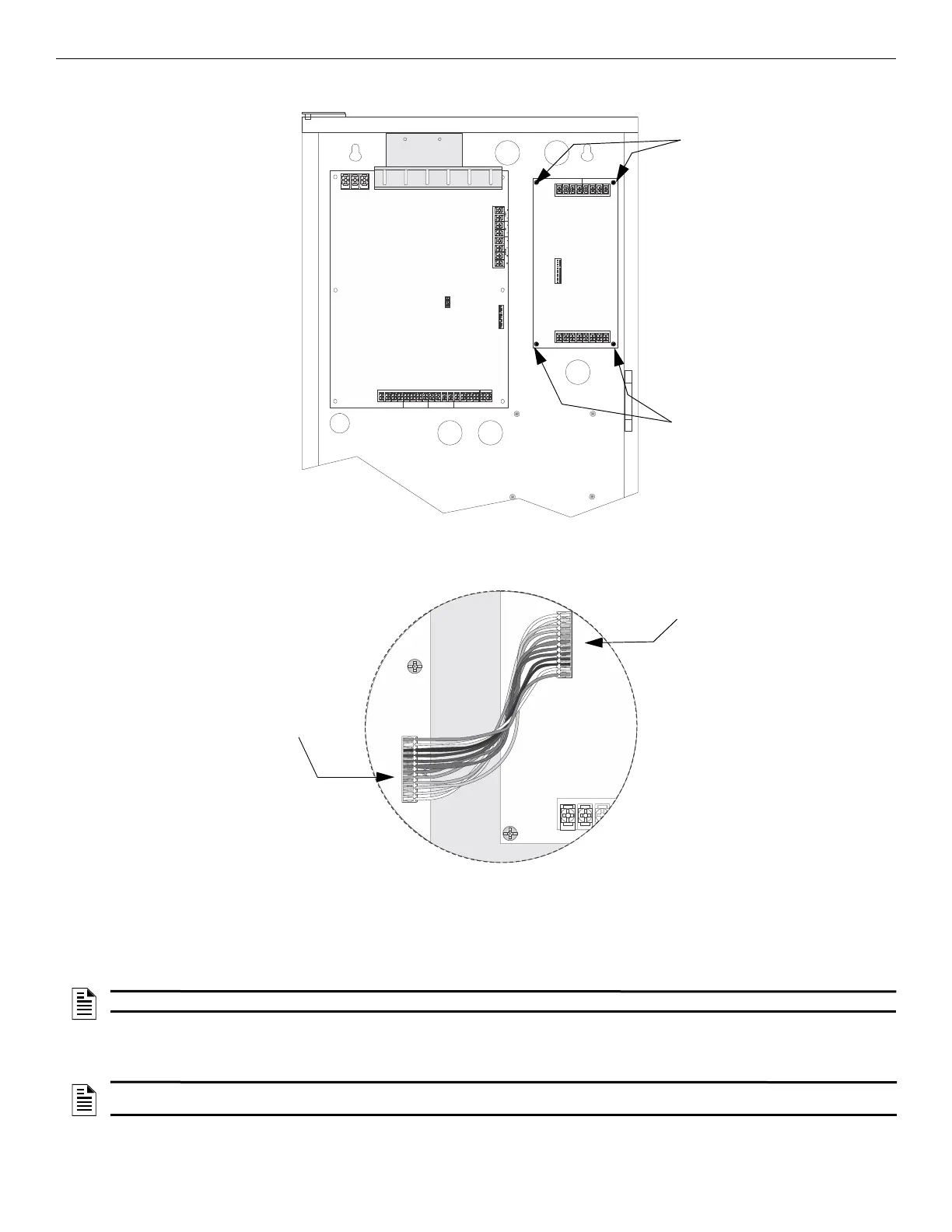
2. Secure the EVS-CE4 to the backbox using the four supplied screws as shown in Figure 4.49.
3. Connect the audio expander cable harness (P/N 130426) from the connector labeled “Audio Expander” on the EVS-50W or EVS-125W
to the connector on the EVS-CE4 as shown in Figure 4.50.
4. Wire audio circuits as shown in “Speaker Wiring” on page 20.
4.9 Installing the EVS-RVM
The EVS-RVM Remote Voice Module is contained within the EVS-RCUor EVS-LOC Local Operator Console. It provides a supervised
microphone for live communication and an interface for the Emergency Communication System.
4.9.1 EVS-RVM Board Layout
The following is description of the EVS-RVM remote voice module components.
CIRCUIT 5 CIRCUIT 6
CIRCUIT 8 CIRCUIT 7
+ OUT –
+ OUT –
+ OUT – + OUT –
+ IN –
+ IN –
+ IN – + IN –
ON
12345
B
A
T
T
E
R
Y
+
–
CIR CUIT 4 CIR CUIT 3 C IRCU IT 2 CIR CUI T 1
IN IN
IN
IN++
+
+––
–
–OUT OUT
OUT
OUT++
+
+––
–
–
AUDIO EXPANDER
B
G
W
EVS-CE4
secure with screws
secure with screws
Figure 4.49 Mounting the EVS-CE4
EVS-CE4
Connector
EVS-50/125W
“Audio Expander”
Figure 4.50 Audio Expander Wire Harness Connections
NOTE: The EVS-RVM is not sold separately.
NOTE: The EVS-VCM and EVS-RVM circuit boards look similar, but they are not interchangeable. The EVS-VCM is mounted in the 5820XL-
EVS and 6820EVS while the EVS-RVM is mounted in the EVS-LOC and EVS-RCU cabinet.

 Loading...


