EVS Series Manual — P/N LS10062-001SK-E:D 3/15/2022 21
Installing the EVS-50W EVS Device Installation
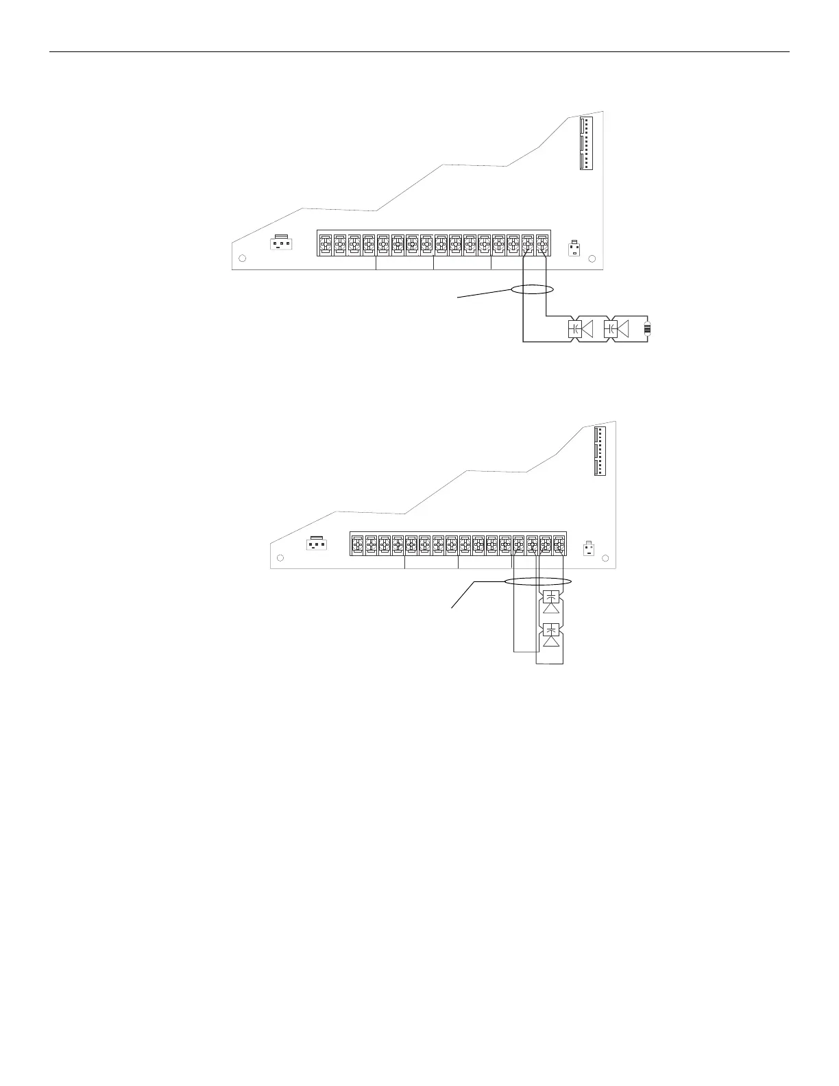
Class B Speaker Configuration
Figure 4.13 illustrates how to wire speakers to the control panel using Class B supervision.
Class A Speaker Configuration
Figure 4.14 illustrates how to wire speakers to the control panel using Class A wiring.
4.3.6 VBUS Wiring
The VBUS is an analog voice bus that carries the recorded voice messages from the EVS-VCM to the EVS-50W, or the voice messages gen-
erated from a system microphone to the EVS-50W. The maximum resistance on the VBUS is 20Ω.
B
A
T
T
E
R
Y
+
–
C IR CU IT 4 CIR C UIT 3 C IR CU IT 2
IN
IN
IN
IN+
+
+
+–
–
–
–OUT
OUT
OUT
OUT+
+
+
+–
–
–
–
AUDIO EXPANDER
supervised,
power-limited
UL-listed
15kΩ EOL
Figure 4.13 Class B Speaker Configuration
B
A
T
T
E
R
Y
+
–
CIR C U IT 4 CIRC U IT 3 CIRC U IT 2
IN
IN
IN
IN
+
+
+
+
–
–
–
–
OUT
OUT
OUT
OUT
+
+
+
+
–
–
–
–
AUDIO EXPANDER
supervised,
power-limited
Figure 4.14 Class A Speaker Configuration

 Loading...


