EVS Series Manual — P/N LS10062-001SK-E:D 3/15/2022 27
Installing the EVS-125W EVS Device Installation
4.5 Installing the EVS-125W
This section provides information on how to install the EVS-125W for use with EVS series products.
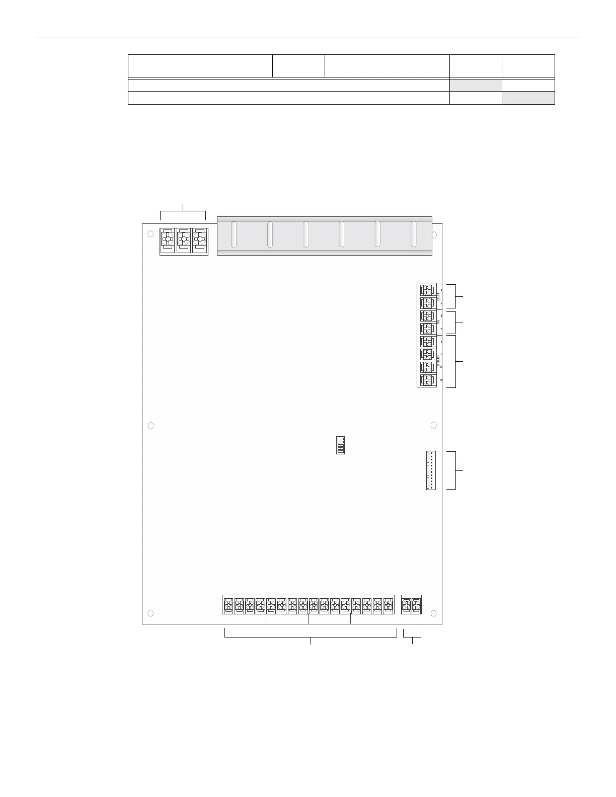
4.5.1 EVS-125W Board Layout
Figure 4.23 shows the location of terminals, DIP switches, and expander connections used in the installation of the EVS-125W.
G Multiply line C (alarm current) and F: Total alarm AH AH
H Add lines E and G (AH = Ampere Hours): Total AH required AH
Device
No. of
Devices
Current Per Device
Standby
Current
Alarm
Current
Table 4.2 Current Draw Calculations
1
IN
IN
IN
IN
+
+
+
+
–
–
–
–
OUT
OUT
OUT
OUT
+
+
+
+
–
–
–
–
AUDIO EXPANDER
B
G
W
audio circuits battery
connector
audio expander
VBUS Out
VBUS In
SBUS
AC connector
Figure 4.23 EVS-125W Board Layout
DIP switch

 Loading...


