EVS Series Manual — P/N LS10062-001SK-E:D 3/15/2022 25
Installing the EVS-INT50W EVS Device Installation
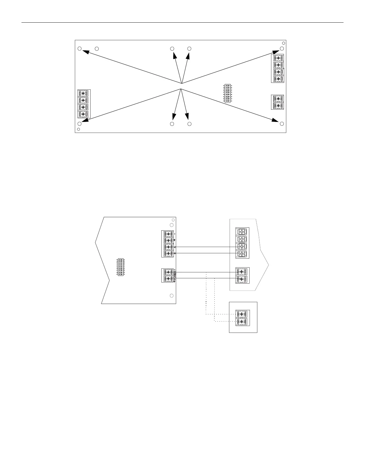
4.4.1 Board Layout & Mounting
Mounting the EVS-INT50W
1. Remove AC power and disconnect the backup batteries from the main control panel.
2. To mount the EVS-INT50W inside the FACP cabinet below the main board, align the board with the mounting holes and secure the
board to the enclosure with the eight supplied screws.
4.4.2 Wiring to an FACP
See Figure 4.21 to properly wire the SBUS and power of the EVS-INT50W to the FACP.
The internal amplifier must be powered by either a NAC programmed as constant auxiliary power or by an auxiliary power supply UL-listed
for fire protective signaling. Refer to the FACP installation manual for more information.
4.4.3 VBUS Wiring
The VBUS is an analog voice bus that carries the recorded voice messages from the EVS-VCM to the EVS-INT50W amplifiers, or the voice
messages generated from a system microphone to the EVS-INT50W.
The maximum resistance on the VBUS is 20Ω.
Figure 4.20 EVS-INT50W Board Layout
VBUS
SBUS
power input
DIP switch
IN1
OUT1
mounting holes
FACP
NAC programmed as
constant aux power
OR
UL-listed aux power
supply
EVS-INT50W
Figure 4.21 Wiring the EVS-INT50W to the FACP
supervised,
power-limited,
Class B

 Loading...


