EVS Series Manual — P/N LS10062-001SK-E:D 3/15/2022 35
Installing the EVS-100W EVS Device Installation
4.6.2 Mounting the EVS-100W
The EVS-100W is equipped with a separate enclosure. Refer to Section 3.1 when selecting a mounting location for the EVS-100W.
The panel should be accessible to main drop wiring runs. It should be mounted as close to the center of the building as possible and located
within a secured area, but should be accessible for testing and service.
Mount the control panel cabinet so it is firmly secured to the wall surface. When mounting on concrete, especially when moisture is
expected, attach a piece of ¾” plywood to the concrete surface and then attach the cabinet to the plywood. Also mount any other modules to
the plywood.
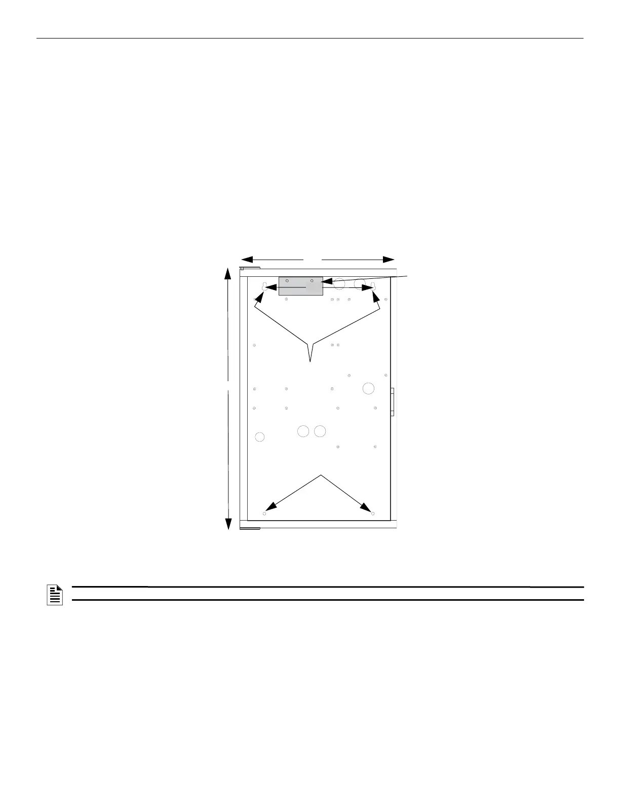
The cabinet can be surface or flush-mounted. If you will be flush-mounting the cabinet, the hole for the enclosure should be 14.5" W x
24.75" H x 3.4375” D (36.8cm W x 62.9cm H x 8.7cm D). Do not flush-mount in a wall designated as a fire break. The outside dimensions
of the cabinet are 16.1" W x 26.5” H x 4.125” D (40.9cm W x 67.3cm H x 10.5cm D).
Follow these steps to properly mount the cabinet.
Follow these steps to properly mount the cabinet.
1. Mark and pre-drill hole in the wall for the center top keyhole mounting bolts using the dimensions below.
2. Install center top fastener in the wall with the screw head protruding.
3. Place backbox over the top screw, level and secure.
4. Mark and drill the lower mounting holes.
5. Install remaining fasteners and tighten.
4.6.3 Mounting the EVS-100WBD Board Only
1. Ensure AC and DC power have been removed from the panel.
2. If this module is a replacement for an existing EVS-100WBD, remove the screws which secure the board to the enclosure.
board mounting bracket
mounting key holes
bottom mounting holes
24.75”
14.5”
11”
Figure 4.35 Cabinet Flush-Mount Dimensions and Mounting Hole Locations
NOTE: Installation and wiring of this device must be done in accordance with NFPA 72 and local ordinances.

 Loading...


