EVS Series Manual — P/N LS10062-001SK-E:D 3/15/2022 37
Installing the EVS-100W EVS Device Installation
4.6.4 Wiring Specifications
All wiring and devices installed in the system must meet the standards described in National Electrical Code (NFPA 70), NFPA Standard 72,
and Life Safety Code (NFPA 101).
To avoid induced noise (transfer of electrical energy from one wire to another), keep input wiring isolated from high-current output and
power wiring. Avoid pulling one multi-conductor cable for the entire panel.
Instead, separate the wiring as follows:
DO NOT pull wires from different groups through the same conduit.
Twisted, shielded wire is recommended for all audio circuits to provide the maximum protection against EMI and AFI emission and suscep-
tibility.
If using shielded cable, attach the shield to earth ground on the control panel.
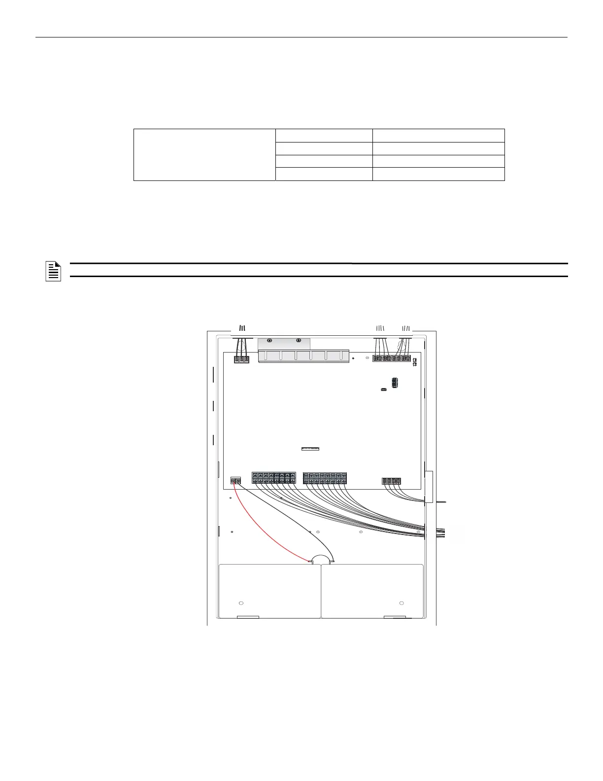
For the same reasons, wiring within the cabinet should be routed around the perimeter of the cabinet. It should not cross the printed circuit
board where it could induce noise into the sensitive microelectronics or pick up unwanted RF noise from the high speed circuits.
High frequency noise, such as that produced by the inductive reactance of a speaker or bell, can also be reduced by running the wire through
ferrite beads or by wrapping it around a ferrite toroid core.
4.6.5 Speaker Wiring
Each EVS-100W supplies eight NACs for speaker connection. The speaker circuit can be supervised and wired Class B or Class A. The
speaker circuits are capable of 50 watts (each) at 25 Vrms or 70.7 Vrms.
Maintain 0.25” spacing between Input/Output Type: Wiring
each of these circuit types; Non Power-Limited: AC power, Standby batteries
as well as between power limited Power-Limited: SBUS, VBUS
and non power-limited circuits. Audio: Speaker
NOTE: Ground Fault Impedance to any Terminal is 0Ω.
Figure 4.38 Wire Routing Example for EVS-100W
AC connection
VBUS
SBUS
audio circuits
battery connection

 Loading...


