EVS Series Manual — P/N LS10062-001SK-E:D 3/15/2022 39
Installing the EVS-100W EVS Device Installation
Class A Speaker Configuration for EVS-100W
Figure 4.40 illustrates how to wire speakers to the control panel using Class A wiring.
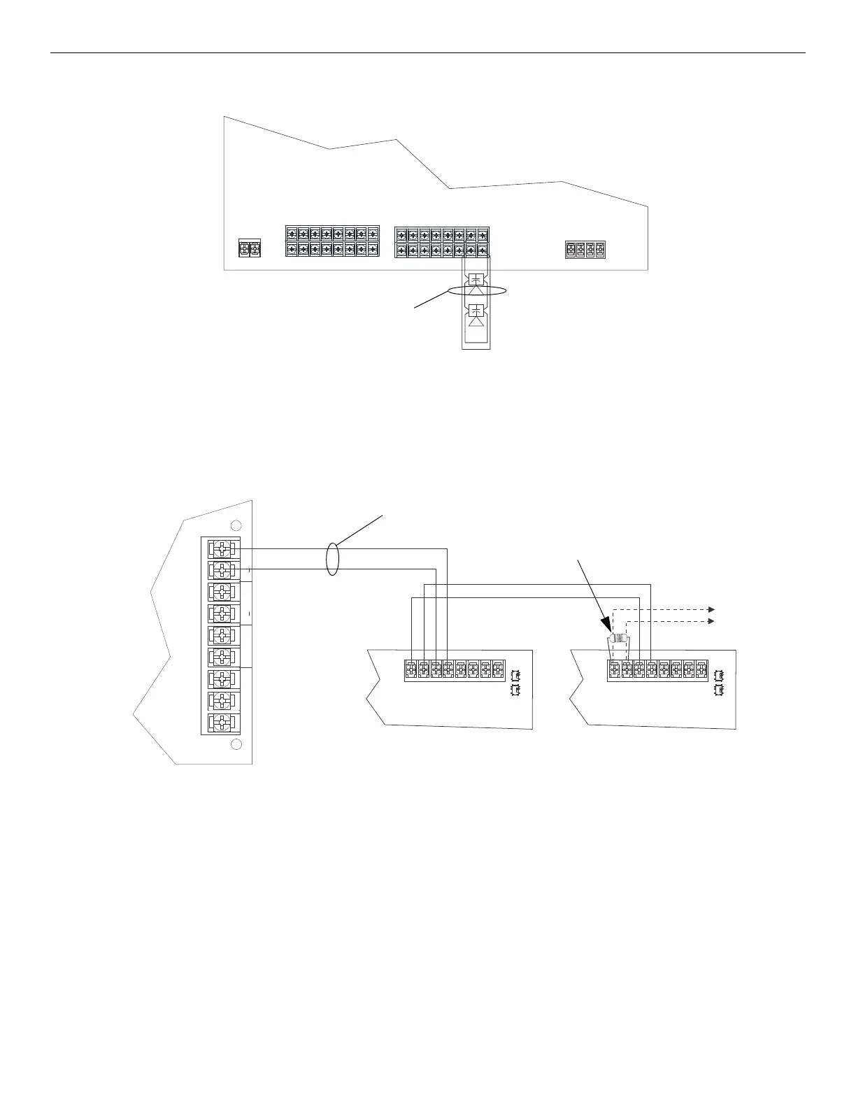
4.6.6 VBUS Wiring
The VBUS is an analog voice bus that carries the recorded voice messages from the EVS-VCM to the EVS-100W amplifiers, or the voice
messages generated from a system microphone to the EVS-100W amplifiers. The maximum resistance on the VBUS is 20Ω.
The EVS-100W supports two VBUS channels. The wiring method is the same for both channels. VBUS1 and VBUS2 should never be wired
together.
Connect the VBUS from the EVS-VCM to the EVS-100W amplifiers as shown in Figure 4.41 and Figure 4.42
supervised,
power-limited
AUDIO CIRCUIT OUT AUDIO CIRCUIT OUT
AUDIO CIRCUIT IN AUDIO CIRCUIT IN
Figure 4.40 Class A Speaker Configuration
AUX
CMD2 CMD1
AUDIO
COMMON
IN
GND
VBUS IN 1
VBUS OUT 1
+
+
Vout1-
Vout1+
Vin1-
Vin1+
Vout2-
Vout2+
Vin2-
Vin2+
Vout1-
Vout1+
Vin1-
Vin1+
Vout2-
Vout2+
Vin2-
Vin2+
EVS-100W
EVS-100W
EVS-VCM
supervised,
power-limited
Class B
to next
EVS-100W
UL-listed 15kΩ
EOL at last device
on the VBUS
Figure 4.41 VBUS Wiring for Single Channel for EVS-VCM

 Loading...


