EVS Series Manual — P/N LS10062-001SK-E:D 3/15/2022 13
Section 4: EVS Device Installation
4.1 Connecting AC Power and Batteries
Refer to the FACP Manual for proper AC and battery power connections. See Section 1.4 on page 8 for reference documentation.
4.2 Installing the EVS-VCM
The EVS-VCM Voice Control Module is contained within the Silent Knight Series EVS panel enclosure. It provides a supervised micro-
phone for live communication and an interface for the Emergency Voice System. This section provides information on how to install or
remove the EVS-VCM to the control cabinet and how to make the proper wiring connections.
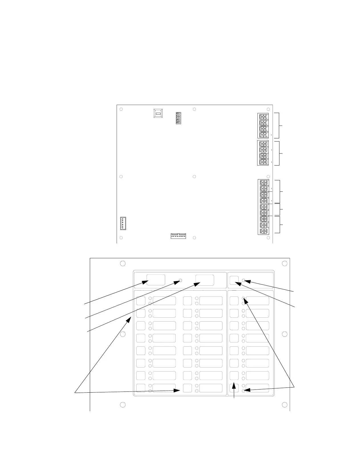
4.2.1 EVS-VCM Board Layout
The following is description of the EVS-VCM voice control module components.
AUX
CMD2 CMD1
AUDIO
COMMON
IN
GND
VBUS 1 IN
USB port
SBUS address
DIP switch
SBUS
VBUS2
VBUS1
aux audio input
aux audio trigger
microphone connector
EVS-SW24
connector
Figure 4.1 Back View of EVS-VCM
NON-ACTIVE
CALL
READY
TO TALK
Figure 4.2 Front View of EVS-VCM
All Call
button
Ready To
Talk LED
Non-Active
Call button
EVS Control
LED
EVS Control
button
output group
select buttons
EVS message 1-8
activate buttons
EVS status/
alarm LEDs

 Loading...


