14 EVS Series Manual — P/N LS10062-001SK-E:D 3/15/2022
EVS Device Installation Installing the EVS-VCM
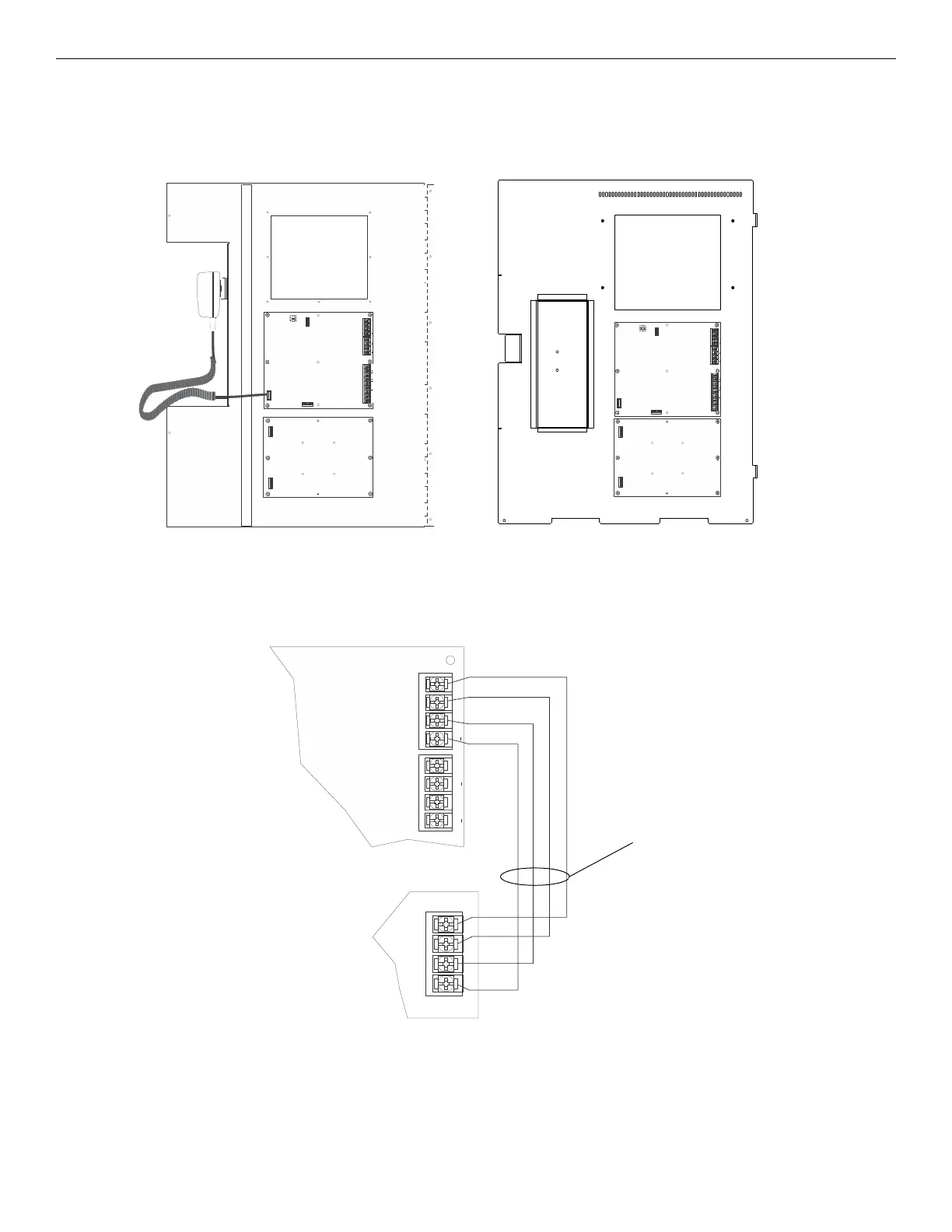
4.2.2 Installing the EVS-VCM
1. Open the cabinet door and the dead front panel.
2. Remove AC power and disconnect the backup batteries from the main control panel.
3. Align the EVS-VCM over the mounting studs in the middle section of the dead front panel and secure with the six supplied nuts with
lockwashers. Refer to the figure below for mounting locations.
4.2.3 Connecting the EVS-VCM to the SBUS
Refer to Figure 4.4 below to properly connect the EVS-VCM to the FACPs SBUS.
See Section 4.10 for instruction on how to set SBUS addressing.
ON
123456
AUX
CMD2 CMD1
AUDIO
COMMON
INGND
VBUS 1 IN
SBUSVBUS 1 OUT
+
+
VBUS 2 IN VBUS 2 OU T
+
+
+
A
B
Figure 4.3 EVS-VCM Mounting Locations
Back view of 5820XL-EVS Dead Front Panel
EVS-VCM
EVS-SW24
ON
123456
AUX
CMD2 CMD1
AUDIO
COMMON
INGND
VBUS 1 IN SBUSVBUS 1 OUT
+
+
VBUS 2 IN
VBUS 2 OUT
+
+
+
AB
Back view of 6820EVS Dead Front Panel
EVS-VCM
EVS-SW24
SBUS
VBUS IN 2
VBUS OUT 2
+
+
+
A
B
SBUS
–+AB
Figure 4.4 EVS-VCM SBUS Connections
EVS-VCM
FACP
supervised,
power-limited
Class B

 Loading...


