32 EVS Series Manual — P/N LS10062-001SK-E:D 3/15/2022
EVS Device Installation Installing the EVS-125W
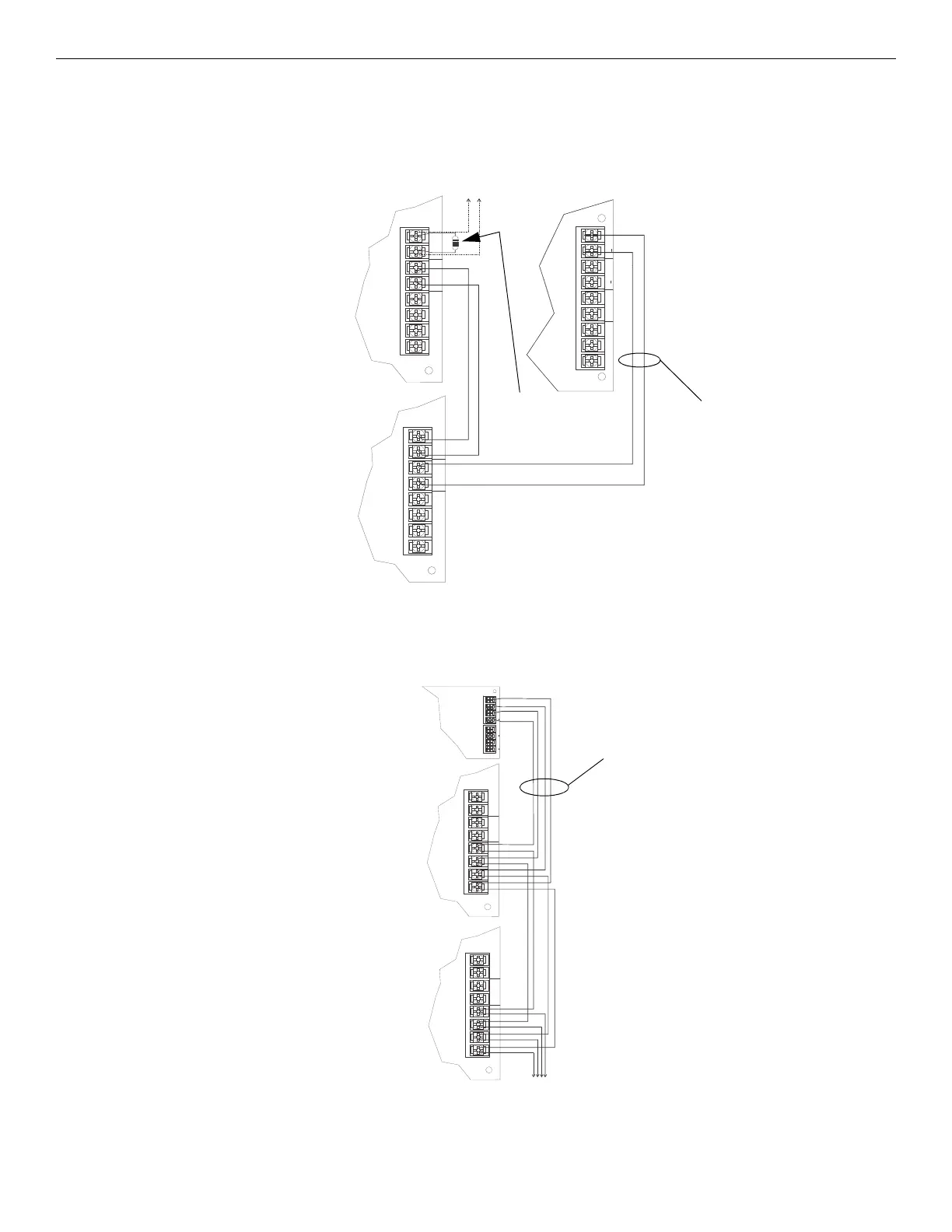
4.5.6 VBUS Wiring
The VBUS is an analog voice bus that carries the recorded voice messages from the EVS-VCM to the EVS-125W or the voice messages
generated from a system microphone to the EVS-125W. The maximum resistance on the VBUS is 20Ω.
Connect the VBUS from the EVS-VCM to the EVS-125W amplifiers as shown in Figure 4.30.
4.5.7 SBUS Wiring
This section contains information on how to connect up to four EVS-125W amplifiers onto the main control SBUS. Refer to Section 4 of the
FACP Installation manual for SBUS specifications. Wire the SBUS as shown in Figure 4.31 using the EVS-VCM.
See Section 4.10 for information on setting SBUS addresses.
OUT
–+
IN
–+
BA+ –
SBUS
OUT
–+
IN
–+
BA+ –
SBUS
AUX
CMD2 CMD1
AUDIO
COMMON
IN
GND
VBUS IN 1
supervised,
power-limited
Class B
EVS-VCM
EVS-125W
EVS-125W
to next
EVS-125W
15KΩ EOL
at last module
on the VBUS
Figure 4.30 VBUS Wiring for EVS-VCM
OUT
–+
IN
–+
BA+ –
SBUS
OUT
–+
IN
–+
BA+ –
SBUS
SBUSVBUS IN 2 VBUS OUT 2
+
+
+
AB
Figure 4.31 Connecting EVS-125W Amplifiers to the SBUS using the EVS-VCM
EVS-125W
EVS-125W
EVS-VCM
to next EVS-125W (max 4)
supervised,
power-limited
Class B

 Loading...


