EVS Series Manual — P/N LS10062-001SK-E:D 3/15/2022 31
Installing the EVS-125W EVS Device Installation
Wiring Lengths
Class B
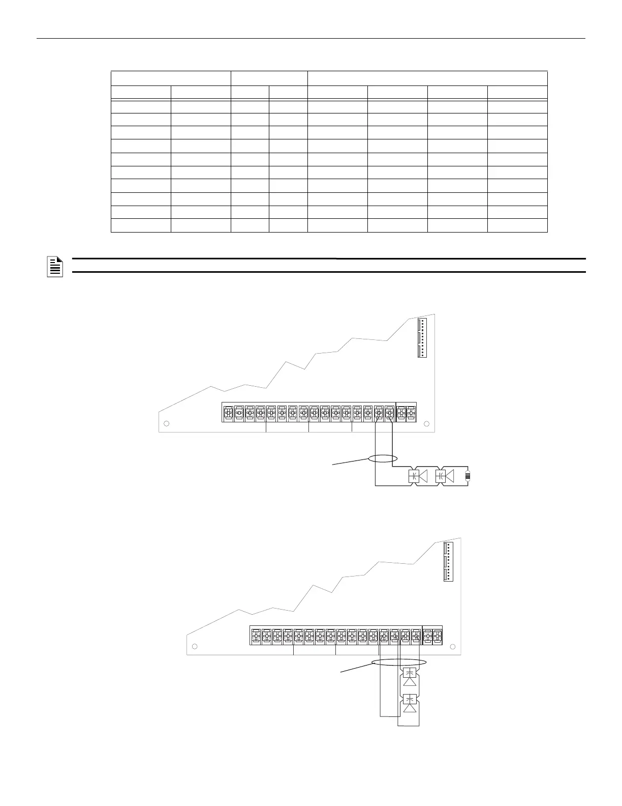
Figure 4.28 illustrates how to wire speakers to the control panel using Class B supervision.
Class A
Figure 4.29 illustrates how to wire speakers to the control panel using Class A wiring.
Number Of Speakers Total Load Wire Distance in Feet
@1/2 W @1 W Vrms Watts 18 AWG 16 AWG 14 AWG 12 AWG
10 5 25Vrms 5W 3900 6200 9860 15680
20 10 25Vrms 10W 2125 3380 5375 8540
30 15 25Vrms 15W 1460 2320 3690 5870
40 20 25Vrms 20W 1100 1750 2780 4420
52 26 25Vrms 26W 760 1200 1920 3050
80 40 25Vrms 40W 550 875 1390 2200
100 50 25Vrms 50W 450 715 1130 1800
150 75 25Vrms 75W 300 476 753 1200
200 100 25Vrms 100W 225 357 565 900
250 125 25Vrms 125W 180 285 452 720
Table 4.3 EVS-125W Wire Lengths
NOTE: The above table assumes a uniform distribution of the speakers, and that a max of 20% voltage drop on the last speaker is allowed.
B
A
T
T
E
R
Y
+
–
CIRCUIT 4 CIRCUIT 3 CIRCUIT 2
IN
IN
IN
IN+
+
+
+–
–
–
–OUT
OUT
OUT
OUT+
+
+
+–
–
–
–
AUDIO EXPANDER
15kΩ EOL
supervised,
power-limited
Figure 4.28 Class B Speaker Configuration
Figure 4.29 Class A Speaker Configuration
supervised,
power-limited

 Loading...


