EVS Series Manual — P/N LS10062-001SK-E:D 3/15/2022 47
Installing the EVS-RVM EVS Device Installation
4.9.2 Wiring the EVS-RVM
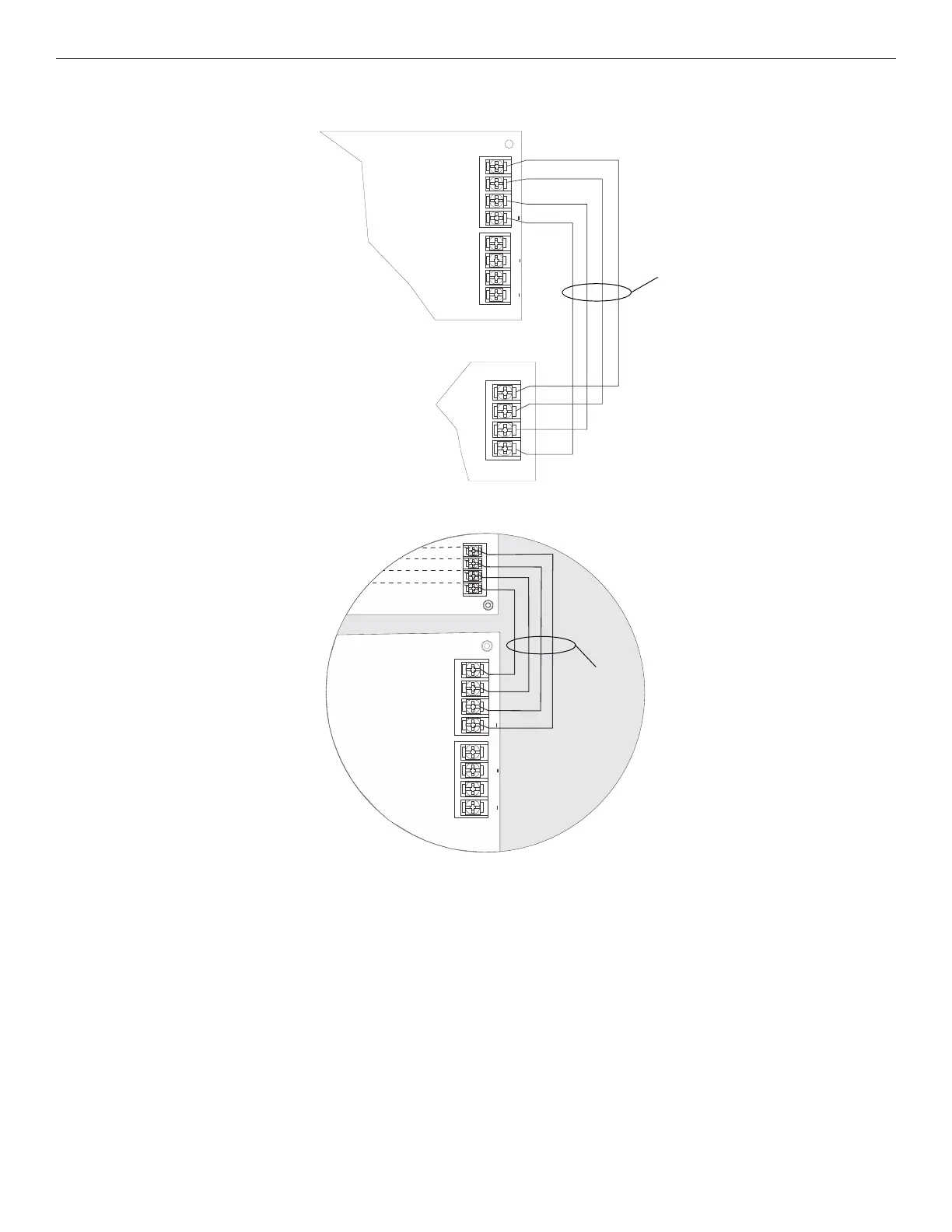
1. Refer to Figure 4.53 to properly connect the EVS-RVM to the FACP’s SBUS.
2. Connect the SBUS to the annunciator and EVS-RVM. See Figure 4.54.
3. Set the SBUS address on the annunciator and the EVS-RVM board. See Section 4.10 for more information.
4. Connect the EVS-RVM to the VBUS, EVS-125W, and EVS-VCM as shown in Figure 4.55.
SBUS
VBUS IN 2
VBUS OUT 2
+
+
+
EVS-RVM
FACP
supervised,
power-limited
Class B
Figure 4.53 EVS-RVM SBUS Connections
SBUS
–AB
+
SBUS
VBUS 2 IN
VBUS 2 OUT
+
+
+
A
B
annunciator
EVS-RVM
SBUS
from previous
SBUS device
Figure 4.54 SBUS wiring for EVS-RVM
supervised,
power-limited
Class B

 Loading...


