EVS Series Manual — P/N LS10062-001SK-E:D 3/15/2022 43
Installing the EVS-100WBU EVS Device Installation
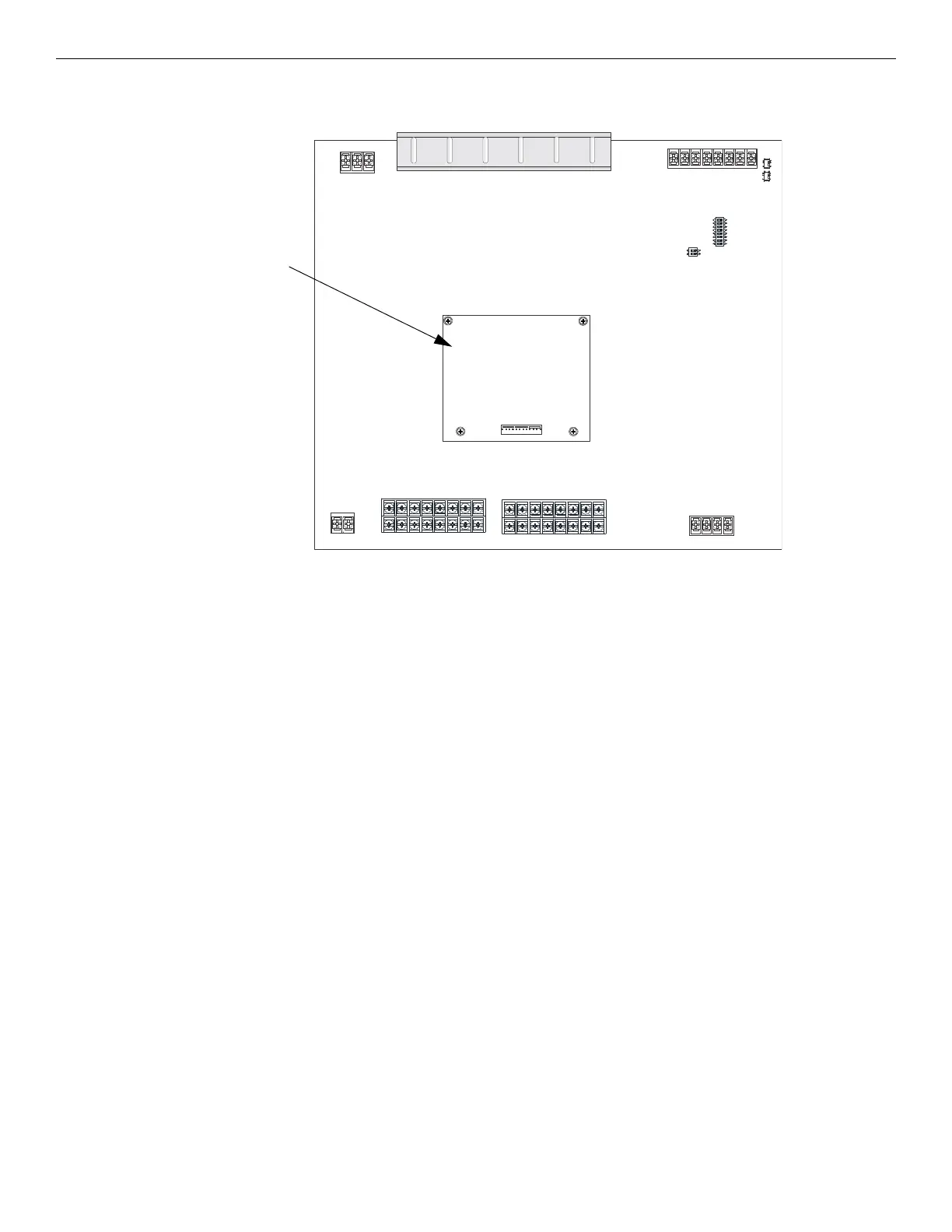
4.7.1 EVS-100W Board Layout
Figure 4.47 shows the location of the EVS-100WBU on the EVS-100W board.
4.7.2 Installing the EVS-100WBU
Follow these steps to install the EVS-100WBU.
1. Ensure all power supplied to the EVS-100W is removed.
2. Secure the four standoffs supplied with the EVS-100W to the board as shown in Figure 4.48.
3. Connect the backup amplifier cable harness (P/N 50116775-001) from the connector labeled “Backup Amplifier” on the EVS-100W to
the connector on the EVS-100WBU.
EVS-100WBU
Figure 4.47 EVS-100WBU Mounting Location

 Loading...


