EVS Series Manual — P/N LS10062-001SK-E:D 3/15/2022 17
Installing the EVS-50W EVS Device Installation
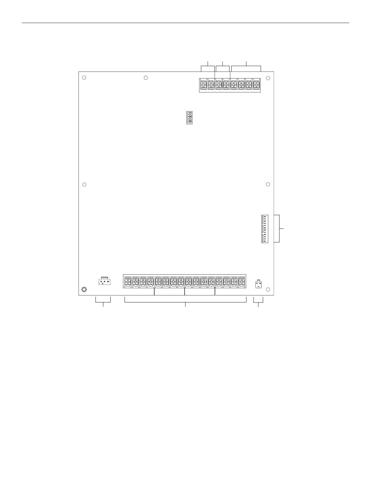
4.3.1 EVS-50W Board Layout
Figure 4.9 shows the location of terminals, DIP switches, and expander connection, used in the installation of the EVS-50W.
4.3.2 Mounting the EVS-50W
The EVS-50W is equipped with a separate enclosure. Refer to Section when selecting a mounting location for the EVS-50W.
The panel should be accessible to main drop wiring runs. It should be mounted as close to the center of the building as possible and located
within a secured area, but should be accessible for testing and service.
Mount the control panel cabinet so it is firmly secured to the wall surface. When mounting on concrete, especially when moisture is
expected, attach a piece of ¾” plywood to the concrete surface and then attach the cabinet to the plywood. Also mount any other modules to
the plywood.
The cabinet can be surface or flush-mounted. If you will be flush-mounting the cabinet, the hole for the enclosure should be 14.5" W x
24.75” H x 3.44” D (36.8cm W x 62.9cm H x 8.7cm D). Do not flush-mount in a wall designated as a fire break. The outside dimensions of
the cabinet are 16" W x 26.5” H x 4.125” D (40.6cm W x 67.3cm H x 10.5cm D).
Follow these steps to properly mount the cabinet.
1. Mark and pre-drill hole in the wall for the center top keyhole mounting bolts using the dimensions below.
2. Install center top fastener in the wall with the screw head protruding.
3. Place backbox over the top screw, level and secure.
4. Mark and drill the lower mounting holes.
OUT
–+
IN
–+–+AB
SBUS
CIRCUIT 4 CIRCUIT 3
1
IN
IN
IN
IN
+
+
+
+
–
–
–
–
OUT
OUT
OUT
OUT
+
+
+
+
–
–
–
–
AUDIO EXPANDER
VBUS
Out In
SBUS
SBUS ID
DIP Switch
Audio
Expander
Battery
Connector
Audio Circuits
AC Transformer
Connector
Figure 4.9 Components Layout of EVS-50W

 Loading...


