EVS Series Manual — P/N LS10062-001SK-E:D 3/15/2022 41
Installing the EVS-100W EVS Device Installation
4.6.9 Test Switches
See Figure 4.34 on page 34 for the location of the Test slide switches.
SW1 - AMP A
Switch should be moved to the “ON” position for normal operation. Move this switch to the “Test” position to test backup amplifier.
SW2 - AMP B
Switch should be moved to the “ON” position for normal operation. Move this switch to the “Test” position to test backup amplifier.
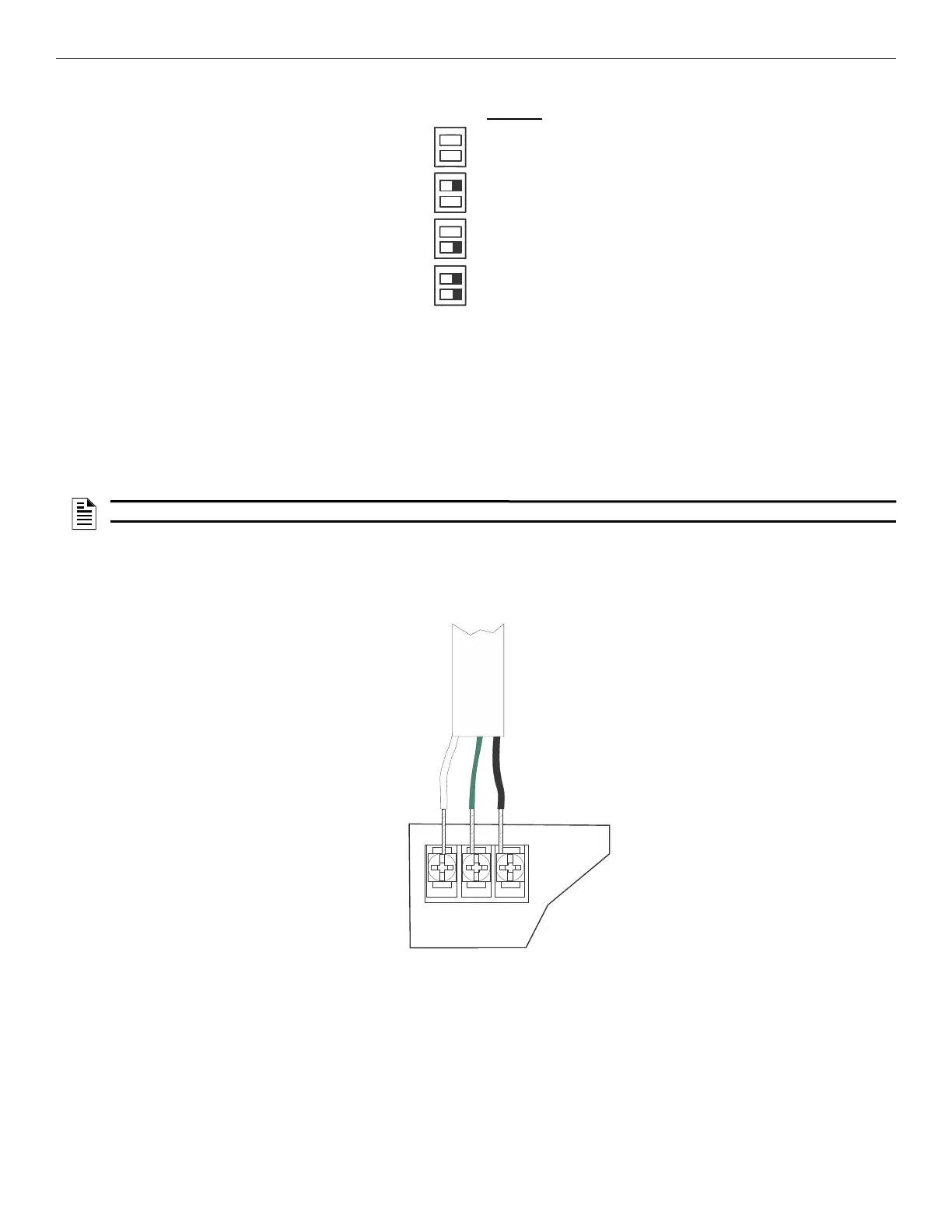
4.6.10 Connecting AC Power
At installation, connect the AC terminals to the power source as shown in Figure 4.45. It may be necessary for a professional electrician to
make this connection.
The AC terminals are rated as 120VAC, 60 Hz.
4.6.11 Backup Battery for EVS-100W
The following steps explain how to connect the batteries (refer to Figure 4.46):
1. Connect the black wire of the battery harness to the (-) side of the battery #2.
2. Connect the jumper wire provided form the positive (+) side of battery #2 to the negative side of battery #1.
Position
(default)
Figure 4.44 DIP Switch Modes
NOTE: Allow up to 3 minutes for backup amplifier to engage.
w
h
i
t
e
g
r
e
e
n
b
l
a
c
k
Figure 4.45 AC Connection

 Loading...


