Installation
10 UDC2300 Universal Digital Controller User Manual 4/00
• Use Suppression Devices—For additional noise protection, you may want to
add suppression devices at the external source. Appropriate suppression
devices are commercially available.
ATTENTION
For additional noise information, refer to Document #51-52-05-01, How to Apply Digital
Instrumentation in Severe Electrical Noise Environments.
Permissible Wiring Bundling
Table 2-5 Permissible Wiring Bundling
Bundle No. Wire Functions
1
• Line power wiring
• Earth ground wiring
• Control relay output wiring
• Line voltage alarm wiring
2
Analog signal wire, such as:
• Input signal wire (thermocouple, 4 to 20 mA, etc.)
• 4-20 mA output signal wiring
Digital input signals
3
• Low voltage alarm relay output wiring
• Low voltage wiring to solid state type control circuits
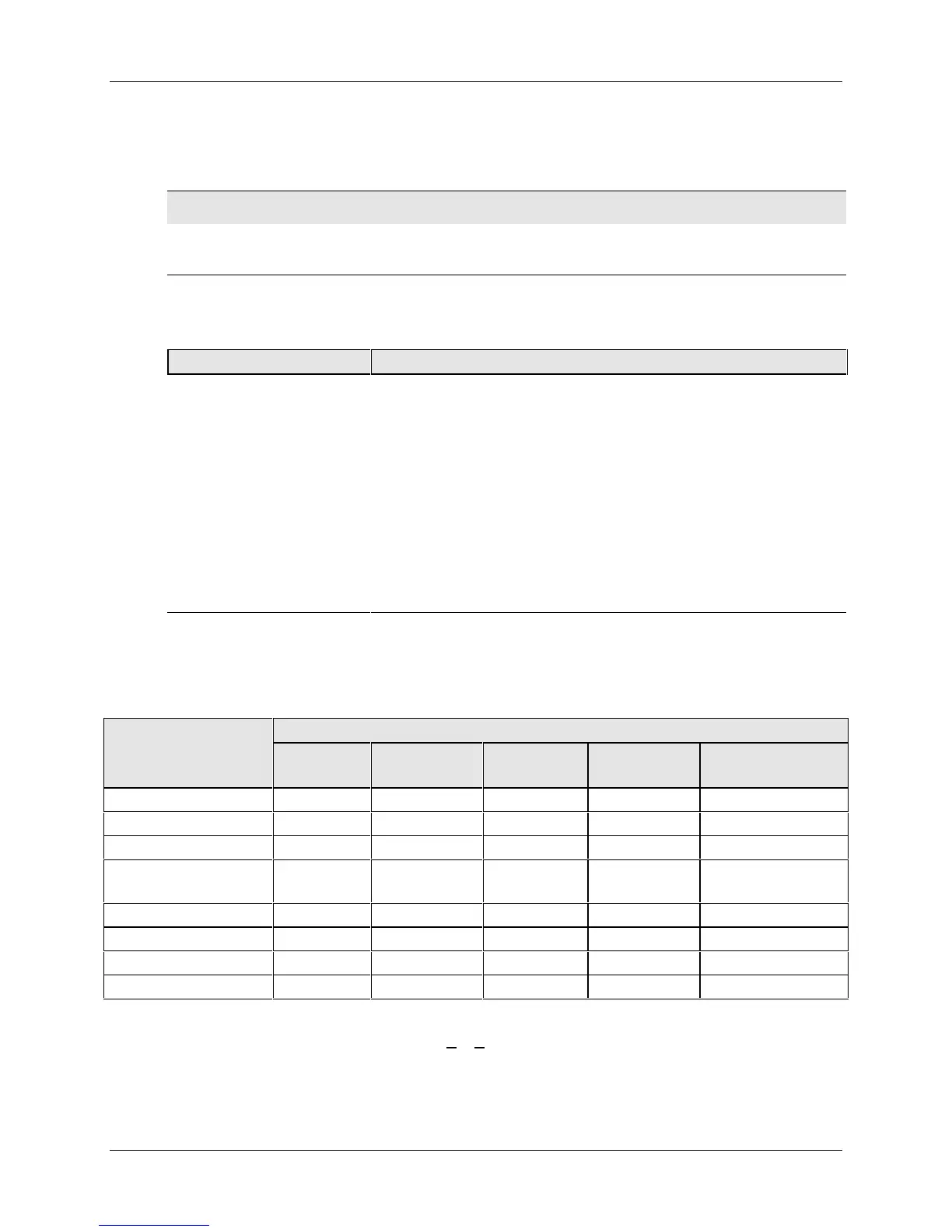
Universal Output Functionality and Restrictions
Table 2-6 Universal Output Functionality and Restrictions
Output/Socket
Output Type Current
Output
Relay #1 Relay #2 Relay #3 Auxiliary Output
Time Simplex 1 N/I Output 1 Alarm 2 Alarm 1 Not Needed
Time Simplex 2 N/A N/I Output 1 Alarm 1 Not Needed
Current Simplex Output N/I Alarm 2 Alarm 1 Not Needed
Time Duplex or
TPSC
N/I Output 1 Output 2 Alarm 1 Not Needed
Current Dup. 100 % Output 1 N/I Alarm 2 Alarm 1 Not Needed
Current Dup. 50 % Output 1 N/I Alarm 2 Alarm 1 Output 2
Current/Time Output 1 N/I Output 2 Alarm 1 Not Needed
Timer/Current Output 2 N/I Output 1 Alarm 1 Not Needed
N/I = Not Installed
N/A = The output form or the individual output is Not A
vailable or is not used for this output form.
Not Needed =Auxiliary Output is not needed to provide the desired output function and can be used for
another purpose. Auxiliary Output could also be used as a substitute for current Output 1.
 Loading...