Installation
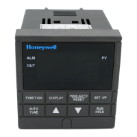
4/00 UDC2300 Universal Digital Controller User Manual 17
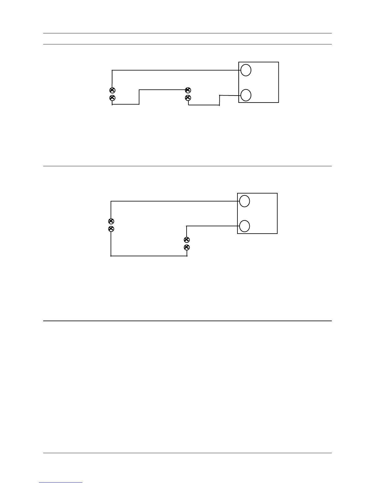
2 Wire Transmitter
Configure:
A2S1TYPE = NONE
A2S2TYPE = NONE
_
+
8 +
7 -
9 –
10+
INPUT 1
OUTPUT 2
Figure 2-16 Transmitter Power for 4-20 mA — 2 wire Transmitter Using Open
Collector Alarm 2 Output (Model DC230B-XT-XX-XX-XXXXXXX-XX-X)
2 Wire Transmitter
Configure:
AUXOUT = OUT
Auxiliary Output Calibration
ZEROVAL = 4095
SPANVAL = 4095
_
+
8 +
7 -
13 +
14 -
INPUT 1
AUXOUT
Figure 2-17 Transmitter Power for 4-20 mA — 2 Wire Transmitter
Using Auxiliary Output (Model DC230B-XX-2X-XX-XXXXXXX-XX-X)
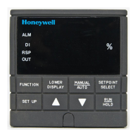
2.7 Initial Start-up
Overview
This section gives you the information necessary to start up your controller prior
to configuration. Review the Operator Interface portion (Subsection 2.8) to make
sure you are familiar with the indicator definitions and key functions.
Apply Power
When power is applied, the controller will run three diagnostic tests. After these
tests are completed, “TEST DONE” is displayed.
 Loading...