Installation
16 UDC2300 Universal Digital Controller User Manual 4/00
9
10
11
12
1 2
Load
Supply
Power
Control or Alarm
Relay #2 Load
Alarm
Relay #1 Load
Load
Supply
Power
5 amp fast Blo
5 amp Fast Blo
24867
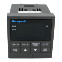
Control relays 1 and 2 are configured N.O. as shipped. Alarm relays 1
and 2 are configured N.C. as shipped. N.O. or N.C. configurations are
selectable by jumpers on main printed wiring boards. See “Preliminar
Checks” in this sections of the User Manual for details. Each SPST
relay is rated at 5 A, 120 Vac and 30 Vdc, 2.5 A, 240 Vac.
Alarm #2 not available for Time Proportional Duplex or Three Position
Step Control.
1
1
2
Figure 2-14 Alarm and Duplex Output Connections
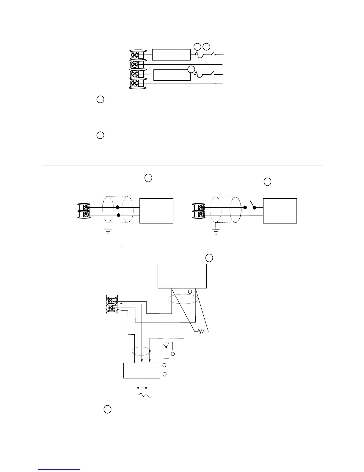
13
14
+
_
Auxiliary
Load
0 - 500
Ω
Connect shield
to ground at one
end only.
1
1
AuxOut , Digital Input and Communications are mutually exclusive.
Auxiliary Output
13
14
+
_
Contact
Input
Switch
Connect shield
to ground at one
end only.
Digital Inputs
1
1
Communications
13
14
D–
D+
COMMUNICATION MASTER
(A) (RTN) (B)
D+
SHLD
D–
120 OHMS
TO OTHER
COMMUNICATION
CONTROLLERS
D+D–
120 OHMS ON LAST LEG
Connect shield wires together with Honeywell
supplied crimp part number 30755381-001
1
2
Do not run these lines in the same conduit as AC power.
1
2
21758B.ppt
Figure 2-15 External Interface Option Connections
 Loading...