Installation
18 UDC2300 Universal Digital Controller User Manual 4/00
Test Failures
If one or more of these tests fail, the controller will go to the Failsafe Manual
Mode, and FAILSF will flash in the lower display and a message indicating which
test failed will appear in the lower display. Then, “DONE” will appear in the lower
display.
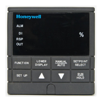
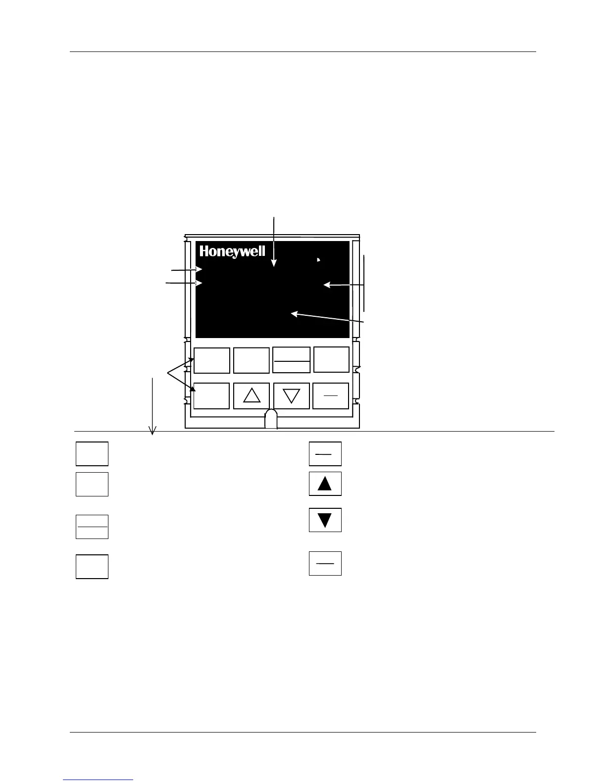
2.8 Operator Interface and Key Functions
ALM
OUT
PV
F
FUNCTION
AUTO
TUNE
MAN-AUTO
RESET
RUN
ALM
- Alarm
conditions exist
OUT
- Control
Relay
1 or 2 on
Keys
C
R
L
1
2
1
2
SP 2300
2300
DISPLAY
M
A
M
or
A -
F
-
C
-
R
setpoint active
L
- Local setpoint active
Upper Display
- Four digits
• Normal operation - Process Variable
• Configuration mode - displays parameter
value or selection
Lower Display
- Six alphanumeric characters
• Normal operation – display is blank unless configured
For default prompt of PV or Setpoint
• Configuration mode - displays functions
and parameters
Selects Manual or Auto mode.
Resets the latching Limit Controller relay.
In Set Up mode, used to restore original value or
selection.
FUNCTION
Selects functions within each configuration group.
Selects 2nd Setpoint or Remote Setpoint.
DISPLAY
Returns Controller to normal display from Set Up
mode.
Toggles various operating parameters for display.
MAN-AUTO
RESET
SET UP
Scrolls through the configuration Setup groups.
Enables Run/Hold of the SP Ramp or Program
setpoint
or output value. Decreases the
configuration values or changes functions in Configuration
setpoint
or output value. Increases the
configuration values or changes functions in Configuration
Initiates Limit Cycle Tuning (Accutune).
24868
RUN
•
TUNE-
Accutune in progress
Figure 2-18 Operator Interface and Key Functions
Key Error Message
When a key is pressed and the prompt KEYERR appears in the lower display, it
will be for one of the following reasons:
• parameter is not available,
• not in Set Up mode, press SET UP key first,
• key malfunction.
 Loading...