Operation
4/00 UDC2300 Universal Digital Controller User Manual 39
4 Operation
4.1 Powering Up the Controller
Apply Power
When power is applied, the controller will run three diagnostic tests. After these
tests are completed, “TEST DONE” is displayed.
Test Failures
If one or more of these tests fail, the controller will go to the Failsafe Manual
Mode, and FAILSF will flash in the lower display and a message indicating which
test failed will appear in the lower display. Then, “DONE” will appear in the lower
display.
4.2 Monitoring Your Controller
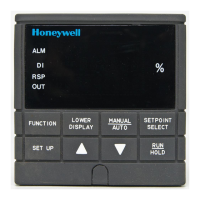
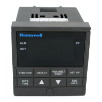
Annunciators
The following annunciator functions have been provided to help monitor the
controller:
Table 4-1 Annunciators
Annunciator Indication
ALM 1 2
A visual indication of each alarm
Blinking 1 indicates alarm latched and needs to be acknowledged
before extinguishing when the alarm condition ends
OUT 1 2
A visual indication of the control relays
A or M
A visual indication of the mode of the controller
A—Automatic Mode
M—Manual Mode
F or C
A visual indication of the temperature units
F—Degrees Fahrenheit
C—Degrees Celsius
L or R
A visual indication of setpoint being used
L— Local Setpoint is active
R— RSP or LSP 2 is active
The upper display is used to show other annunciator functions
TUNE—Accutuning in progress
RUN—SP Program in progress
HOLD—SP Program on hold
CSP—Controlling to the Computer Setpoint
LOOPBK—Loopback test running
 Loading...