Installation
4/00 UDC2300 Universal Digital Controller User Manual 11
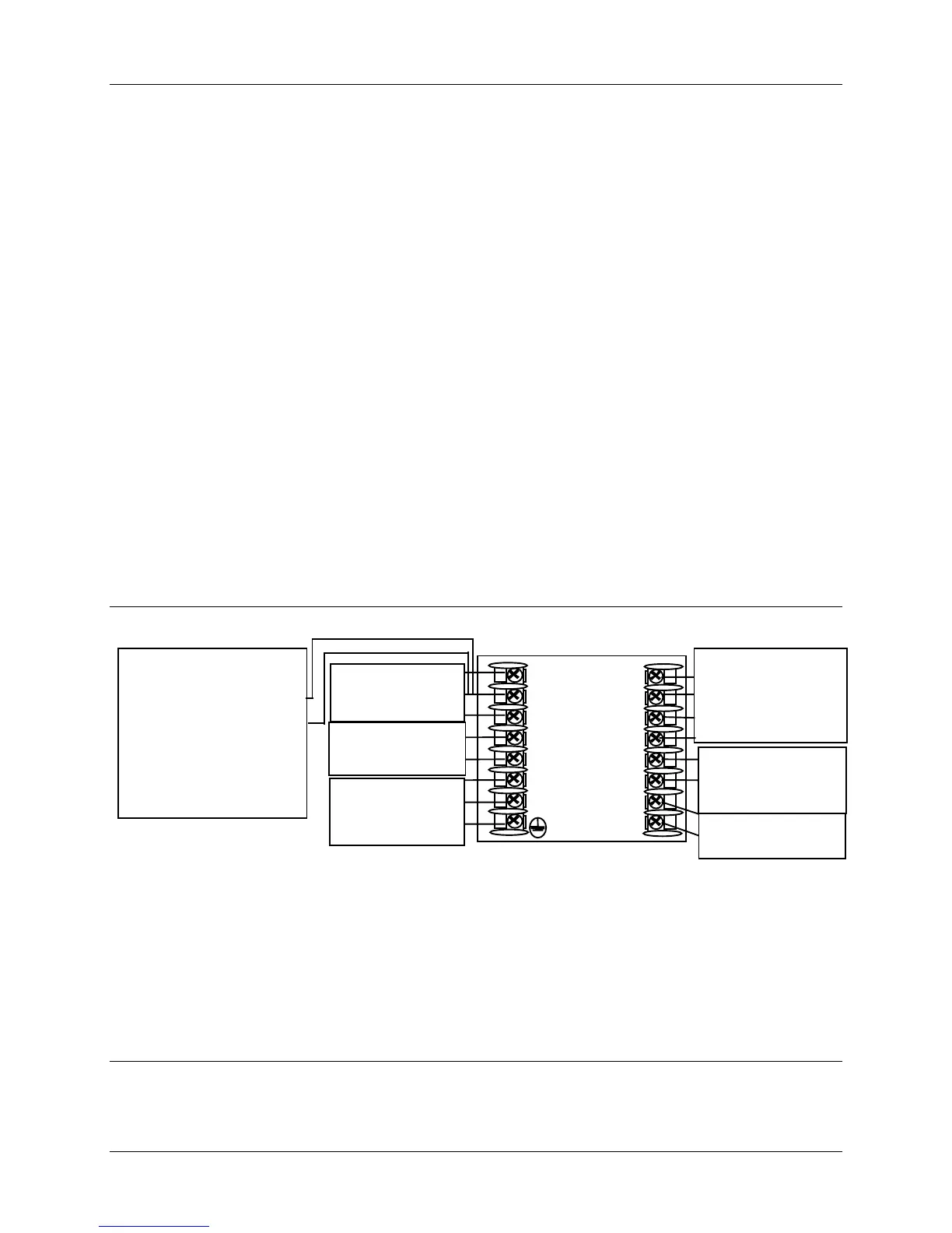
2.6 Wiring the Controller
Using the information contained in the model number, select the appropriate
wiring diagrams from the composite wiring diagram below. Refer to the individual
diagrams listed to wire the controller according to your requirements.
Composite Wiring Diagram
Mains Power Supply
Input 1 Connections
Input 2 Connections
Relay Output
Electromechanical
Solid State
Open Collector
Current Output Connections
External Solid State Relay Output Option
Three Position Step Control Connections
Alarm and Duplex Output Connections
External Interface Option Connections
Transmitter Power for 4-20mA – 2-Wire Transmitter
Using Open Collector Alarm 2 Output
Transmitter Power for 4-20mA – 2-Wire Transmitter
Using Auxiliary Output
11
12
12
12
13
13
14
14
15
15
16
16
17
17
9
10
11
12
13
14
15
16
7
6
5
4
L2 / N
L1
8
Input
Terminal
See Figure 2-6
Control Output
Terminals
See Note 1
Mains Power
Supply Terminals
See Figure 2-5
Input #2 Terminals
See Figure 2-7
External Interface
Options Terminals
See Figure 2-15
Alarm and
Duplex Output
Connections
See Figure 2-14
24855
Transmitter Power for
4-20 mA 2-wire
transmitters
•
Using Alarm Output
See Figure 2-16
• Using Aux Output
See Figure 2-17
Time Proportional Electromechanical Relay Output – See Figure 2-8
Time Proportional Solid State Relay Output – See Figure 2-9
Time Proportional Open Collector Output – See Figure 2-10
Current Output – See Figure 2-11
External Solid State Relay Output – See Figure 2-12
Three Position Step Control Output – See Figure 2-13
NOTE1:
Figure 2-4 Composite Wiring Diagram
 Loading...