Installation
4/00 UDC2300 Universal Digital Controller User Manual 13
1
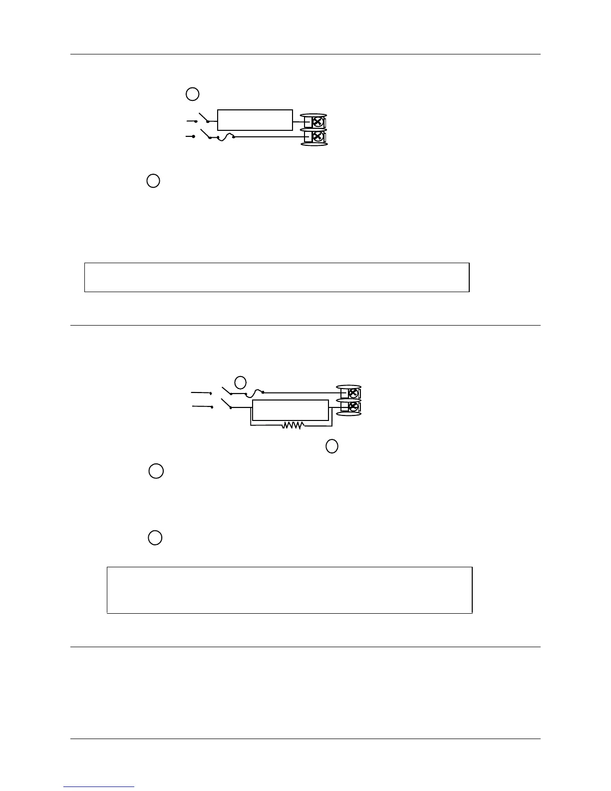
Control relays 1 and 2 are configured N.O. as shipped. Alarm relays
1 and 2 are configured N.C. as shipped. N.O. or N.C. configurations
are selectable by jumpers on the Main printed wiring boards.
See “Preliminary Checks” in this section of the
User Manual for details.
Each SPST relay is rated at 5A, 120
Vac and 30 Vdc, 2.5 A 240 Vac. User-provided fuses should be sized
accordingly. For solid state relay outputs, see Figure 2-12.
24859
1
5
4
Load
Supply
Power
5 amp Fast Blo
Control Relay #1
Load
OUT1 OUT2/ALM2
9
10
See Figure 2-14 for Alarm and Duplex Output Connections.
See Table 2-2 and Table 2-3 for Control and Alarm Relay Contact information.
Figure 2-8 Electromechanical Relay Output
If the load current is less than the minimum rated value of 20 mA,
there may be a residual voltage across both ends of the load even
if the relay is turned off. Use a dummy resistor as shown to
counteract this. The total current through the resistor and the load
current must exceed 20 mA.
2
1
Solid State relay is rated at 1 Amp at 25°C, linearly derated to 0.5
Amp at 55°C. Customer should size fuse accordingly.
5
4
AC
Load
Power
Supply
Dummy Resistor
2
1
24860
Control Relay #1
Load
1 amp Fast Blo
OUT1 OUT2/ALM2
9
10
See Figure 2-14 for Alarm and Duplex Output Connections.
See Table 2-2 and Table 2-3 for Control and Alarm Relay Contact
information.
Figure 2-9 Solid State Relay Output
 Loading...