1.
Find
the
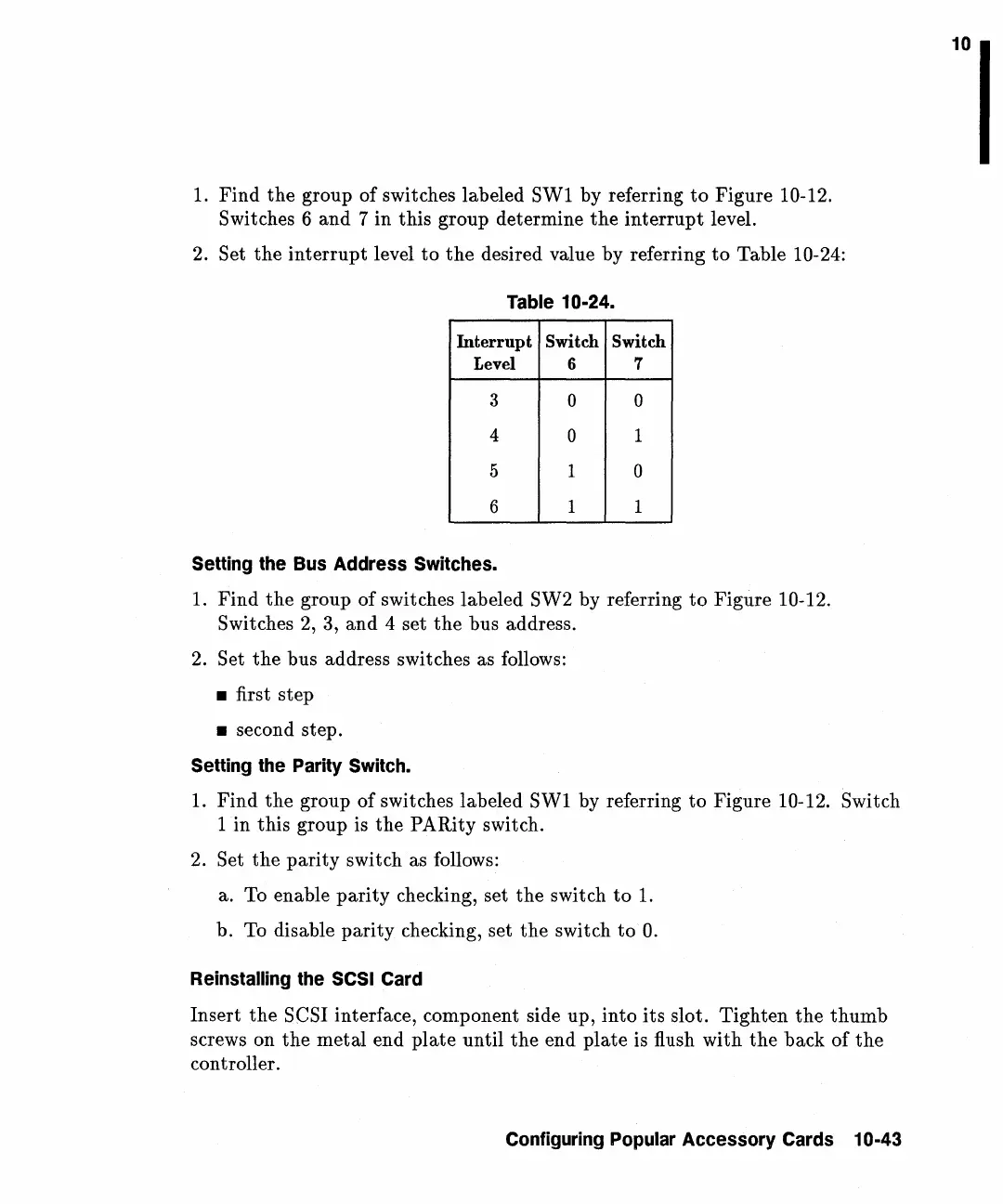
group of switches labeled SW1 by referring
to
Figure 10-12.
Switches 6
and
7 in this group determine
the
interrupt
level.
2.
Set
the
interrupt
level
to
the
desired value by referring
to
Table 10-24:
Table 10-24.
mterrupt Switch Switch
Level
6 7
3
0 0
4
0
1
5 1
0
6
1 1
Setting the Bus Address Switches.
1.
Find
the
group of switches labeled SW2 by referring
to
Figure 10-12.
Switches
2,
3,
and
4 set
the
bus address.
2.
Set
the
bus address switches as follows:
• first step
• second step.
Setting the Parity Switch.
1.
Find
the
group of switches labeled SW1 by referring
to
Figure 10-12. Switch
1
in
this group is
the
PARity switch.
2.
Set
the
parity
switch as follows:
a. To enable
parity
checking, set
the
switch
to
1.
b. To disable
parity
checking, set
the
switch
to
O.
Reinstalling the SCSI Card
Insert
the
SCSI interface, component side up,
into
its
slot. Tighten
the
thumb
screws on
the
metal
end
plate
until
the
end
plate
is flush with
the
back of
the
controller.
Configuring Popular Accessory Cards 10-43
10
 Loading...