6
Example 5 - Increased Tuning Linearity
18 pm, which is larger than the 1 pm tolerance allowed in this example. The
measured wavelength reading is therefore sent to the TLS using the HP-IB
command
WAVEACT
.
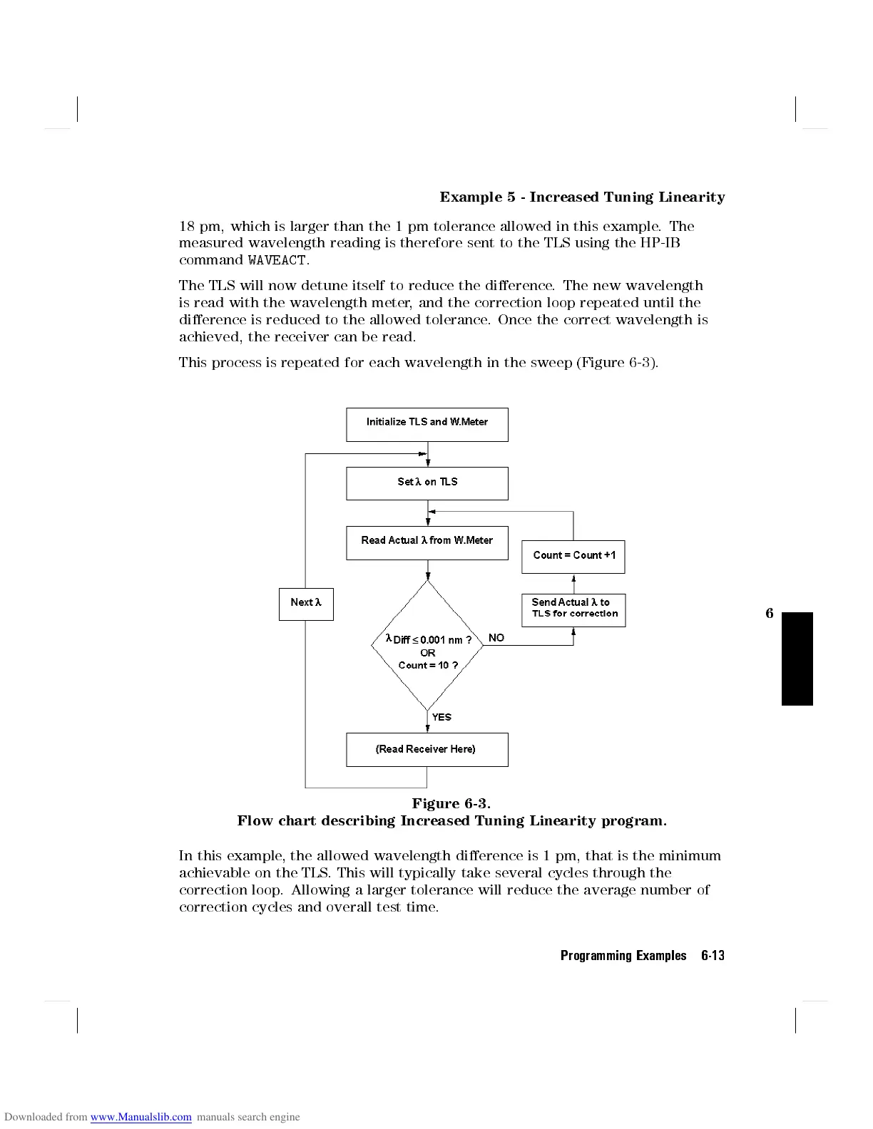
The TLS will now detune itself to reduce the dierence. The new wavelength
is read with the wavelength meter, and the correction loop repeated until the
dierence is reduced to the allowed tolerance. Once the correct wavelength is
achieved, the receiver can be read.
This process is repeated for each wavelength in the sweep (Figure 6-3 ).
Figure 6-3.
Flow chart describing Increased Tuning Linearity program.
In this example, the allowed wavelength dierence is 1 pm, that is the minimum
achievable on the TLS. This will typically take several cycles through the
correction loop. Allowing a larger tolerance will reduce the average number of
correction cycles and overall test time.
Programming Examples 6-13