Overview
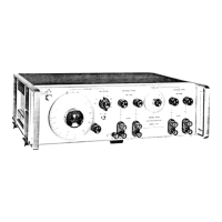
The HP 8647A signal generator covers the frequency range
of
0.25 to
1000
MHz
in three bands. The frequency bands are:
0.25 to 249 MHz
249 to 501 MHz
501 to 1000
MHz
The output amplitude is from
+
10 to
-
136 dBm. The HP 8647A
supports
AM,
FM, and phase modulation.
The possible sources are:
Internal
400
Hz
or 1 kHz source.
External ac- or dc-coupled source.
Internal 1 kHz plus external dc-coupled source.
A1
Front
Panel
The front panel contains two RPGs (rotary pulse generator), the
keyboard, and the
LCD
display.
The two RPGs, one for frequency and one for amplitude, are
connected directly to the controller on the
A3
board. Each RPG
receives power and ground from the controller. Each RPG returns two
out-of-phase pulsed lines when the knob is turned.
The keyboard is a matrix of keys
as
shown in Table 5a-1. The
keyboard is scanned by the controller. Scanning pulses are sent
alternately to the keyboard rows and are read back on the columns
when a key is pressed. The controller determines which key was
pressed based on the row that was pulsed and the column that the
signal was returned on. The column lines are pulled-up through
resistors and are pulsed low when a key is pressed. The row output
latches are open-collector, therefore, pulses can not be seen until the
circuit is completed by pressing a key. The keyboard connects directly
to the controller at A3J3.
The display is driven by the controller through data latches on the
A3
assembly. The display control lines are eight bi-directional data lines,
an
enable clock line, a read/write line, and a datdinstruction line. The
other lines going to the display are the backlight +5
V
and ground,
display +5
V
and ground, and the contrast control. The enable
clock line is high during every data interchange. The read/write
line is high for a read operation and low for a write operation. The
datdinstruction line is high for a data operation and low for an
instruction operation. The datdinstruction line is used only during
write operations. Data refers to the character data while instruction
refers to commands, such
as
return or space. When interchanging
data, the controller polls the display for acknowledgement. This
means that if the display is disconnected the controller
will
cease to
attempt operations.
5a.2 Theory
of
Operation