4–4 361288-003 Service Reference Guide, dc7100
Serial and Parallel ATA Drive Guidelines and Features
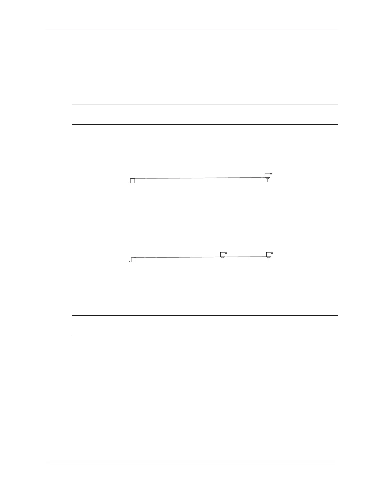
4.2.5 PATA Cable Layout
The faces of industry-standard cable connectors are color-coded for easy recognition:
■ System board connector = blue face
■ Device 0 connector = black face
■ Device 1 connector = gray face
✎
The color code of an industry-standard cable is applicable only if the drive’s jumper is in the
cable-select position.
Single-Drive Cable
Two-Drive Cable
On a two-drive cable, the Drive/Device 0 connector is always the farthest one from the system
board connector and the Drive/Device 1 connector is always the closest to the system board
connector.
✎
Some cables may be labeled “Drive 0” instead of “Device 0” and “Drive 1” instead of
“Device 1”.
System
Board
Device 0
Black
Face
Blue
Face
System
Board
Device 1
Device 0
Black
Face
Blue
Face
Gray
Face
 Loading...