109
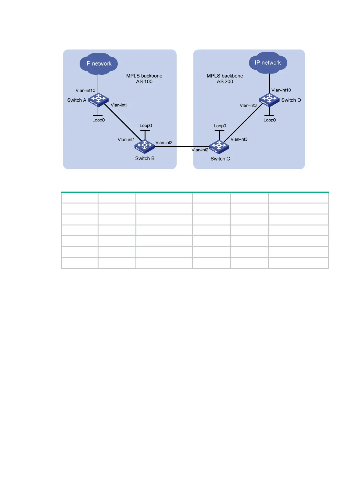
Figure 32 Network diagram
Table 4 Interface and IP address assignment
Device Interface IP address Device Interface IP address
Switch A Loop0 1.1.1.9/32 Switch D Loop0 4.4.4.9/32
Vlan-int1 10.1.1.1/24 Vlan-int3 30.1.1.2/24
Vlan-int10 100.1.1.1/24 Vlan-int10 100.1.2.1/24
Switch B Loop0 2.2.2.9/32 Switch C Loop0 3.3.3.9/32
Vlan-int1 10.1.1.2/24 Vlan-int3 30.1.1.1/24
Vlan-int2 20.1.1.1/24 Vlan-int2 20.1.1.2/24
407BConfiguration procedure
1. Configure IP addresses and masks for interfaces. (Details not shown.)
2. Configure OSPF to advertise routes within the ASs, and redistribute the direct and BGP routes
into OSPF on Switch B and Switch C:
# Configure Switch A.
<SwitchA> system-view
[SwitchA] ospf
[SwitchA-ospf-1] area 0
[SwitchA-ospf-1-area-0.0.0.0] network 10.1.1.0 0.0.0.255
[SwitchA-ospf-1-area-0.0.0.0] network 1.1.1.9 0.0.0.0
[SwitchA-ospf-1-area-0.0.0.0] quit
[SwitchA-ospf-1] quit
# Configure Switch B.
<SwitchB> system-view
[SwitchB] ospf
[SwitchB-ospf-1] import-route direct
[SwitchB-ospf-1] import-route bgp
[SwitchB-ospf-1] area 0
[SwitchB-ospf-1-area-0.0.0.0] network 10.1.1.0 0.0.0.255
[SwitchB-ospf-1-area-0.0.0.0] network 2.2.2.9 0.0.0.0

 Loading...


