136
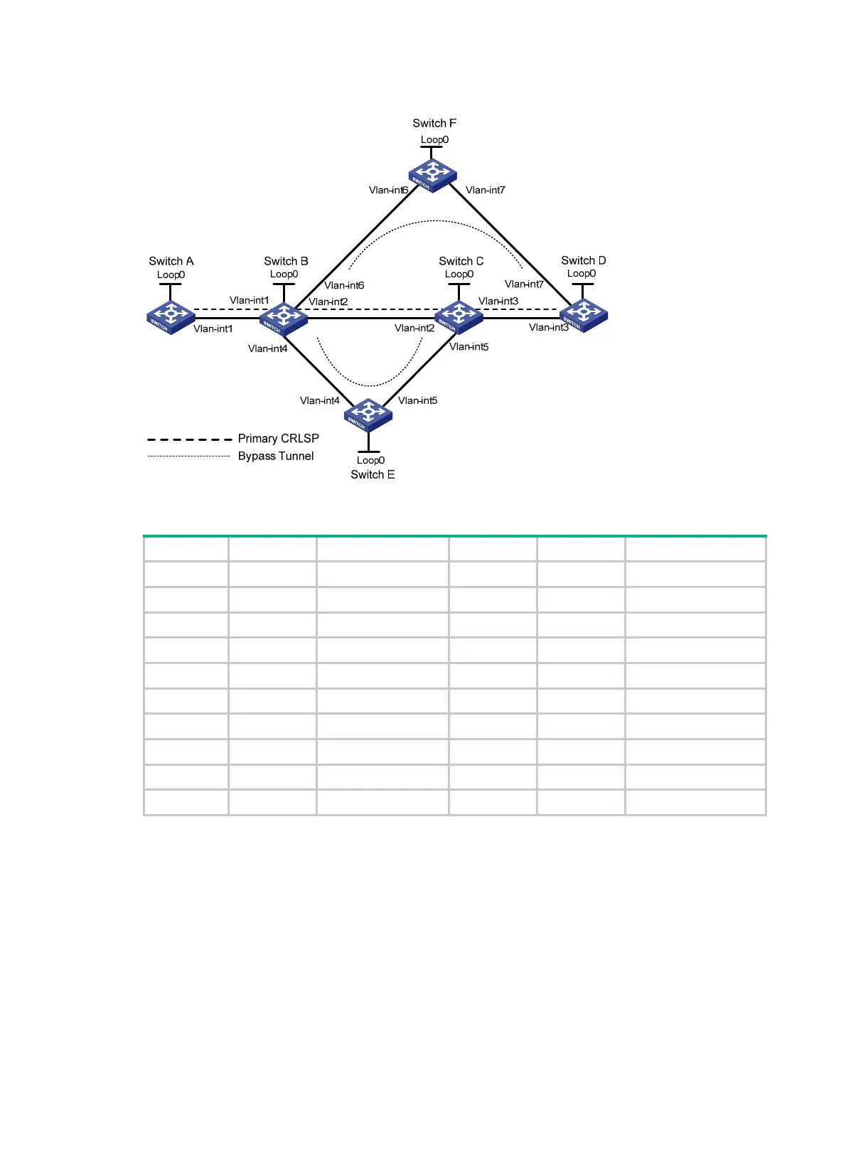
Figure 37 Network diagram
Table 8 Interface and IP address assignment
Device Interface IP address Device Interface IP address
Switch A Loop0 1.1.1.1/32 Switch E Loop0 5.5.5.5/32
Vlan-int1 2.1.1.1/24 Vlan-int4 3.2.1.2/24
Switch B Loop0 2.2.2.2/32 Vlan-int5 3.4.1.1/24
Vlan-int1 2.1.1.2/24 Switch C Loop0 3.3.3.3/32
Vlan-int2 3.1.1.1/24 Vlan-int3 4.1.1.1/24
Vlan-int4 3.2.1.1/24 Vlan-int2 3.1.1.2/24
Vlan-int6 3.3.1.1/24 Vlan-int5 3.4.1.2/24
Switch D Loop0 4.4.4.4/32 Switch F Loop0 6.6.6.6/32
Vlan-int3 4.1.1.2/24 Vlan-int6 3.3.1.2/24
Vlan-int7 4.2.1.2/24 Vlan-int7 4.2.1.1/24
422BConfiguration procedure
Before configuration, disable the spanning tree feature globally or map each VLAN to an MSTI. For
more information, see Layer 2—LAN Switching Configuration Guide.
1. Configure IP addresses and masks for interfaces. (Details not shown.)
2. Configure IS-IS to advertise interface addresses, including the loopback interface address.
(Details not shown.)
3. Configure an LSR ID, and enable MPLS, MPLS TE, and RSVP-TE on each switch. Enable BFD
for RSVP-TE on Switch B and Switch C:
# Configure Switch A.
<SwitchA> system-view
[SwitchA] mpls lsr-id 1.1.1.1

 Loading...


