234
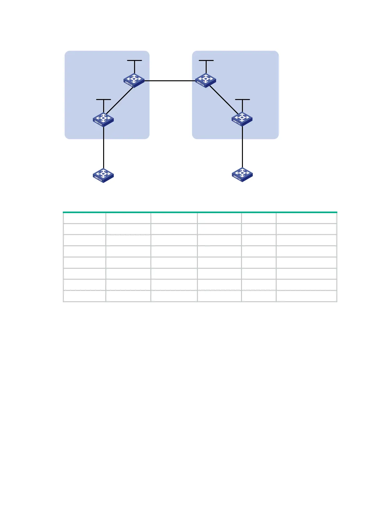
Figure 68 Network diagram
Table 14 Interface and IP address assignment
Device Interface IP address Device Interface IP address
CE 1 Vlan-int12 10.1.1.1/24 CE 2 Vlan-int12 10.2.1.1/24
PE 1 Loop0 1.1.1.9/32 PE 2 Loop0 4.4.4.9/32
Vlan-int12 10.1.1.2/24 Vlan-int12 10.2.1.2/24
Vlan-int11 172.1.1.2/24 Vlan-int11 162.1.1.2/24
ASBR-PE 1 Loop0 2.2.2.9/32 ASBR-PE 2 Loop0 3.3.3.9/32
Vlan-int11 172.1.1.1/24 Vlan-int11 162.1.1.1/24
Vlan-int12 192.1.1.1/24 Vlan-int12 192.1.1.2/24
481BConfiguration procedure
1. Configure IGP on the MPLS backbone to implement the connectivity in the backbone.
This example uses OSPF. (Details not shown.)
# Execute the display ospf peer command to verify that each ASBR-PE has established an
OSPF adjacency in Full state with the PE in the same AS, and that PEs and ASBR-PEs in the
same AS have learned the routes to the loopback interfaces of each other. Verify that each
ASBR-PE and the PE in the same AS can ping each other. (Details not shown.)
2. Configure basic MPLS and MPLS LDP on the MPLS backbone to establish LDP LSPs:
# Configure basic MPLS on PE 1, and enable MPLS LDP on the interface connected to
ASBR-PE 1.
<PE1> system-view
[PE1] mpls lsr-id 1.1.1.9
[PE1] mpls ldp
[PE1-ldp] quit
[PE1] interface vlan-interface 11
[PE1-Vlan-interface11] mpls enable
[PE1-Vlan-interface11] mpls ldp enable
[PE1-Vlan-interface11] quit
Loop0 Loop0
Loop0 Loop0
Vlan-int12
CE 1 CE 2
AS 65001 AS 65002
PE 1
PE 2
ASBR-PE 2
ASBR-PE 1
MPLS backbone
MPLS backbone
AS 100
AS 200
Vlan-int12
Vlan-int12
Vlan-int12
Vlan-int11
Vlan-int11
Vlan-int12Vlan-int12
Vlan-int11
Vlan-int11

 Loading...


