244
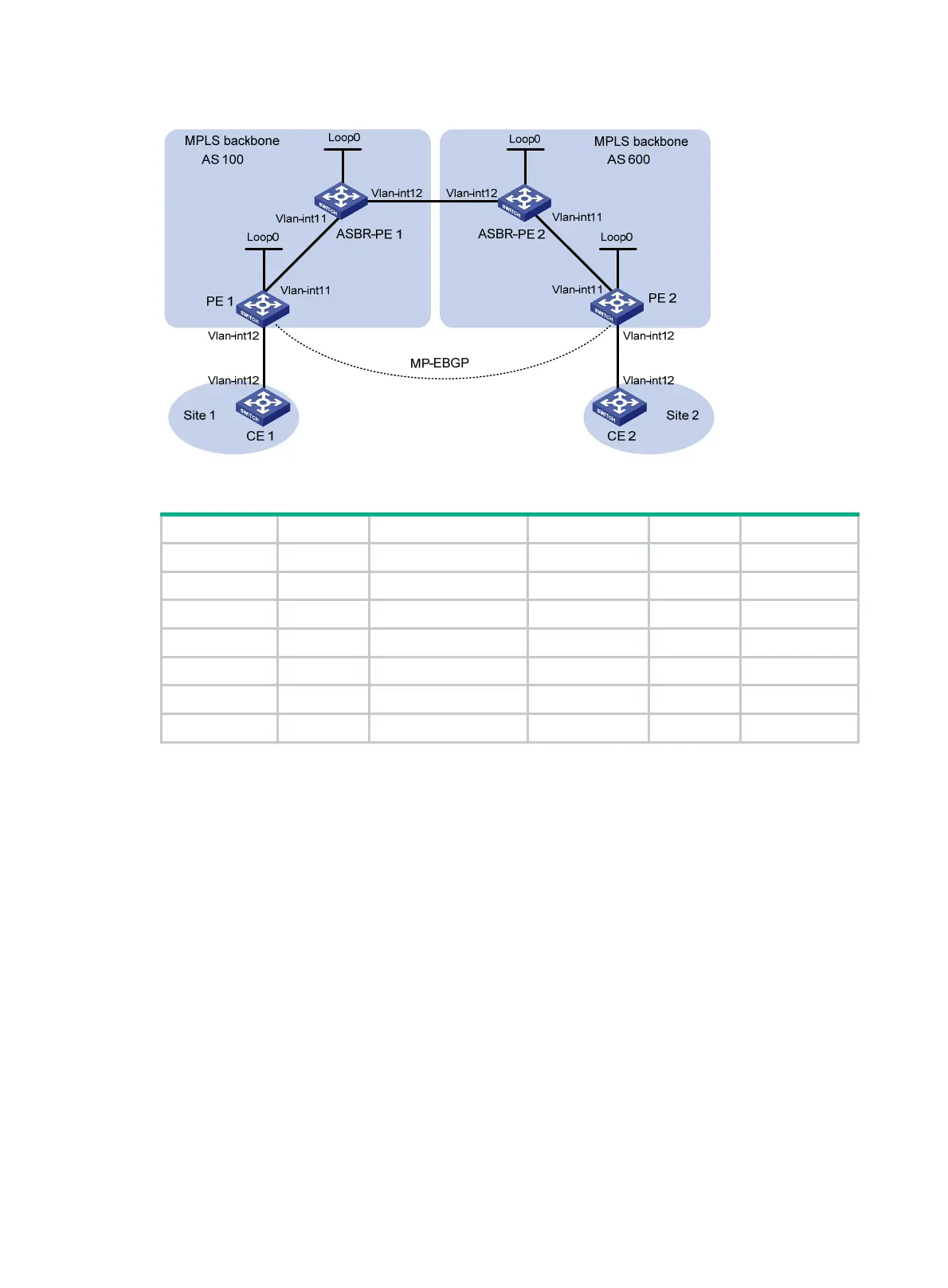
Figure 70 Network diagram
Table 16 Interface and IP address assignment
Device Interface IP address Device Interface IP address
PE 1 Loop0 2.2.2.9/32 PE 2 Loop0 5.5.5.9/32
Vlan-int11 1.1.1.2/8 Vlan-int11 9.1.1.2/8
Vlan-int12 30.0.0.1/24 Vlan-int12 20.0.0.1/24
ASBR-PE 1 Loop0 3.3.3.9/32 ASBR-PE 2 Loop0 4.4.4.9/32
Vlan-int11 1.1.1.1/8 Vlan-int11 9.1.1.1/8
Vlan-int12 11.0.0.2/8 Vlan-int12 11.0.0.1/8
CE 1 Vlan-int12 30.0.0.2/24 CE 2 Vlan-int12 20.0.0.2/24
487BConfiguration procedure
1. Configure CE 1:
# Configure an IP address for VLAN-interface 12.
<CE1> system-view
[CE1] interface vlan-interface 12
[CE1-Vlan-interface12] ip address 30.0.0.2 24
[CE1-Vlan-interface12] quit
# Establish an EBGP peer relationship with PE 1, and redistribute VPN routes.
[CE1] bgp 65001
[CE1-bgp-default] peer 30.0.0.1 as-number 100
[CE1-bgp-default] address-family ipv4 unicast
[CE1-bgp-default-ipv4] peer 30.0.0.1 enable
[CE1-bgp-default-ipv4] import-route direct
[CE1-bgp-default-ipv4] quit
[CE1-bgp-default] quit
2. Configure PE 1:
# Configure IS-IS on PE 1.
<PE1> system-view

 Loading...


