266
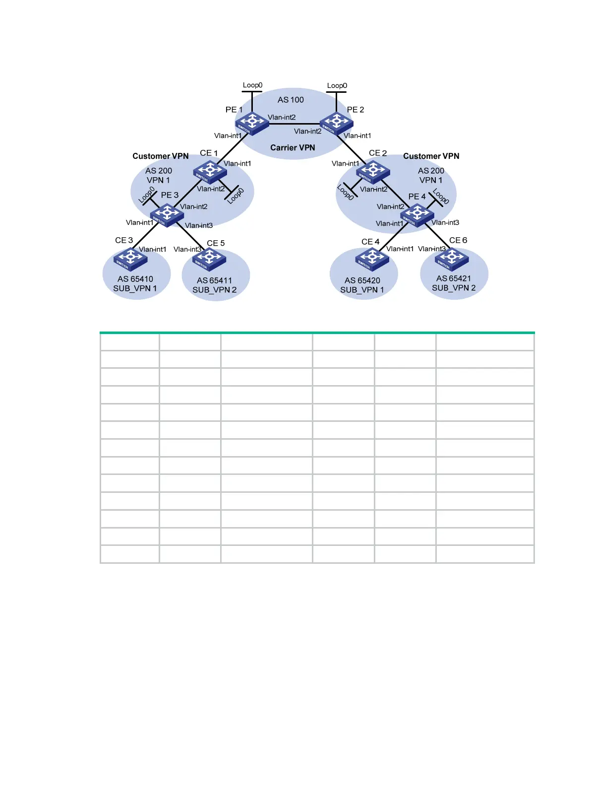
Figure 73 Network diagram
Table 19 Interface and IP address assignment
Device Interface IP address Device Interface IP address
CE 1 Loop0 2.2.2.9/32 CE 2 Loop0 5.5.5.9/32
Vlan-int2 10.1.1.2/24 Vlan-int1 21.1.1.2/24
Vlan-int1 11.1.1.1/24 Vlan-int2 20.1.1.1/24
CE 3 Vlan-int1 100.1.1.1/24 CE 4 Vlan-int1 120.1.1.1/24
CE 5 Vlan-int3 110.1.1.1/24 CE 6 Vlan-int3 130.1.1.1/24
PE 1 Loop0 3.3.3.9/32 PE 2 Loop0 4.4.4.9/32
Vlan-int1 11.1.1.2/24 Vlan-int1 21.1.1.1/24
Vlan-int2 30.1.1.1/24 Vlan-int2 30.1.1.2/24
PE 3 Loop0 1.1.1.9/32 PE 4 Loop0 6.6.6.9/32
Vlan-int1 100.1.1.2/24 Vlan-int1 120.1.1.2/24
Vlan-int2 10.1.1.1/24 Vlan-int2 20.1.1.2/24
Vlan-int3 110.1.1.2/24 Vlan-int3 130.1.1.2/24
496BConfiguration procedure
1. Configure MPLS L3VPN on the service provider backbone. Use IS-IS as the IGP protocol,
enable LDP, and establish an MP-IBGP peer relationship between PE 1 and PE 2:
# Configure PE 1.
<PE1> system-view
[PE1] interface loopback 0
[PE1-LoopBack0] ip address 3.3.3.9 32
[PE1-LoopBack0] quit
[PE1] mpls lsr-id 3.3.3.9
[PE1] mpls ldp
[PE1-ldp] quit

 Loading...


