282
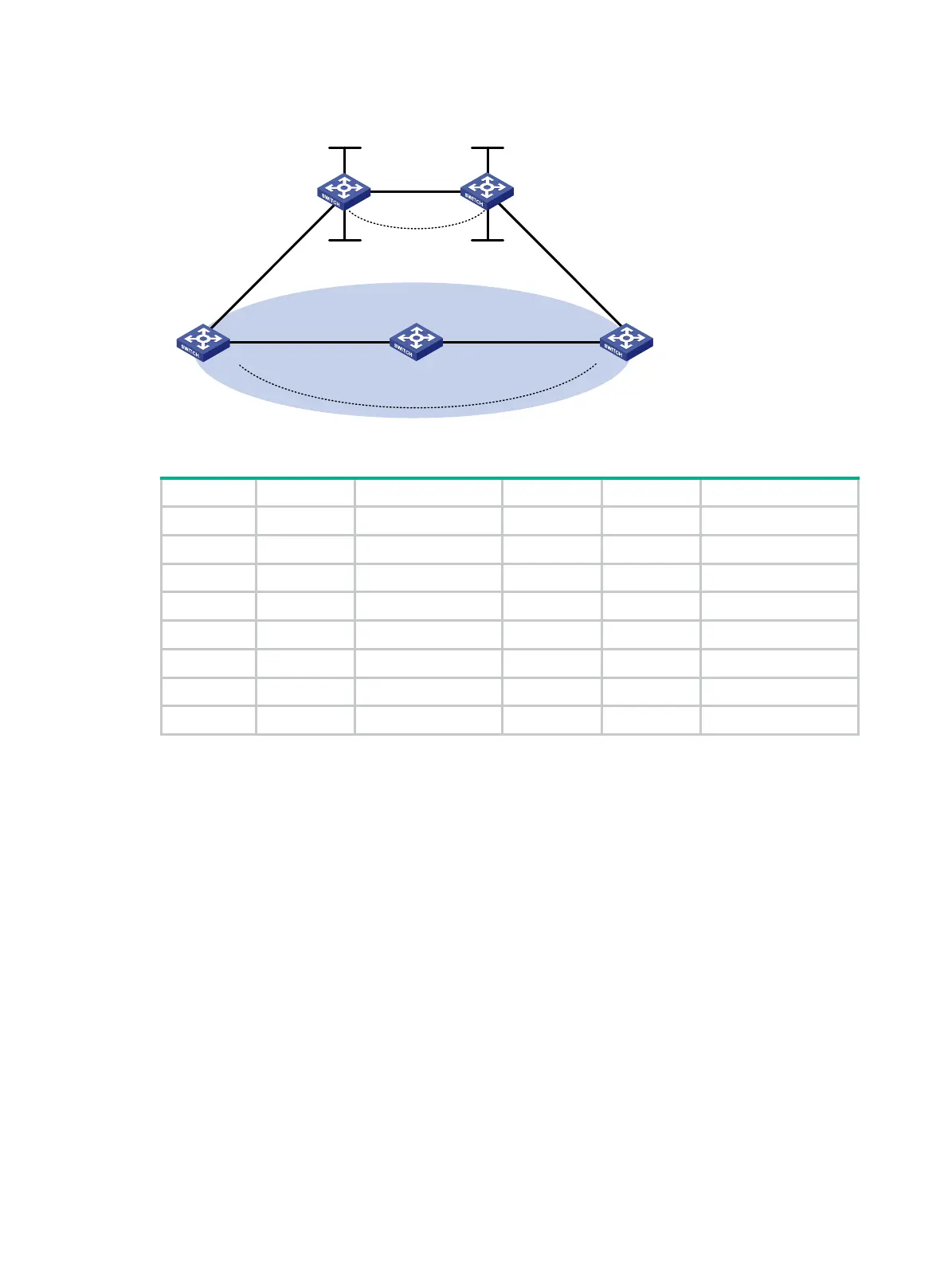
Figure 75 Network diagram
Table 21 Interface and IP address assignment
Device Interface IP address Device Interface IP address
CE 1 Vlan-int11 100.1.1.1/24 CE 2 Vlan-int11 120.1.1.1/24
Vlan-int13 20.1.1.1/24 Vlan-int12 30.1.1.2/24
PE 1 Loop0 1.1.1.9/32 PE 2 Loop0 2.2.2.9/32
Loop1 3.3.3.3/32 Loop1 5.5.5.5/32
Vlan-int11 100.1.1.2/24 Vlan-int11 120.1.1.2/24
Vlan-int12 10.1.1.1/24 Vlan-int12 10.1.1.2/24
Switch A Vlan-int11 20.1.1.2/24
Vlan-int12 30.1.1.1/24
502BConfiguration procedure
1. Configure OSPF on the customer networks:
# Configure conventional OSPF on CE 1, Switch A, and CE 2 to advertise subnet addresses of
the interfaces (see
814HTable 21). (Details not shown.)
# Set the cost value to 2 for both the link between CE 1 and Switch A, and the link between CE
2 and Switch A. (Details not shown.)
# Execute the display ip routing-table command to verify that CE 1 and CE 2 have learned the
route to each other. (Details not shown.)
2. Configure MPLS L3VPN on the backbone:
# Configure basic MPLS and MPLS LDP on PE 1 to establish LDP LSPs.
<PE1> system-view
[PE1] interface loopback 0
[PE1-LoopBack0] ip address 1.1.1.9 32
[PE1-LoopBack0] quit
[PE1] mpls lsr-id 1.1.1.9
[PE1] mpls ldp
[PE1-ldp] quit
[PE1] interface vlan-interface 12
[PE1-Vlan-interface12] ip address 10.1.1.1 24
Vlan-int12
Loop0
Loop0
Sham-link
CE 1 Switch A CE 2
PE 2PE 1
Loop1 Loop1
OSPF Area 1
Backdoor link
Vlan-int12
Vlan-int11
Vlan-int11
Vlan-int13
Vlan-int11
Vlan-int11
Vlan-int12 Vlan-int12
Vlan-int13

 Loading...


