290
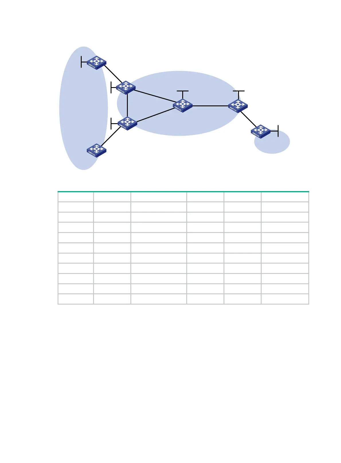
Figure 77 Network diagram
Table 23 Interface and IP address assignment
Device Interface IP address Device Interface IP address
CE 1 Loop0 100.1.1.1/32 CE 3 Loop0 200.1.1.1/32
Vlan-int2 10.1.1.1/24 Vlan-int7 10.3.1.1/24
CE 2 Vlan-int2 10.2.1.1/24 PE 2 Loop0 2.2.2.9/32
PE 1 Loop0 1.1.1.9/32 Vlan-int2 10.2.1.2/24
Vlan-int2 10.1.1.2/24 Vlan-int4 40.1.1.2/24
Vlan-int3 30.1.1.1/24 Vlan-int5 50.1.1.1/24
Vlan-int4 40.1.1.1/24 P Loop0 3.3.3.9/32
PE 3 Loop0 4.4.4.9/32 Vlan-int3 30.1.1.2/24
Vlan-int6 60.1.1.2/24 Vlan-int5 50.1.1.2/24
Vlan-int7 10.3.1.2/24 Vlan-int6 60.1.1.1/24
508BConfiguration procedure
1. Configure basic MPLS L3VPN:
{ Configure OSPF on the MPLS backbone to allow the PEs and P device to learn the routes
of the loopback interfaces from each other.
{ Configure basic MPLS and MPLS LDP on the MPLS backbone to establish LDP LSPs.
{ Establish an MP-IBGP peer relationship between the PEs to advertise VPN IPv4 routes.
{ Configure the VPN instance of VPN 1 on PE 1 to allow CE 1 to access the network.
{ Configure the VPN instance of VPN 1 on PE 2 to allow CE 2 to access the network.
{ Configure the VPN instance of VPN 1 on PE 3 to allow CE 3 to access the network.
{ Configure BGP as the PE-CE routing protocol, and redistribute routes of the CEs into the
PEs.
For more information about basic MPLS L3VPN configurations, see "
817HConfiguring basic MPLS
L3VPN."
Loop0
Loop0
Loop0
PE 1
P
PE 3
CE 2
CE 3
VPN 1
AS 600
VPN 1
AS 600
Vlan-int6
Vlan-int6
Vlan-int7
Vlan-int2
Vlan-int2
MPLS backbone
AS 100
CE 1
Vlan-int2
Vlan-int2
Loop0
Vlan-int4
Vlan-int3
PE 2
Vlan-int4
Vlan-int5
Vlan-int3
Vlan-int5
Vlan-int7
Loop0
Loop0

 Loading...


