317
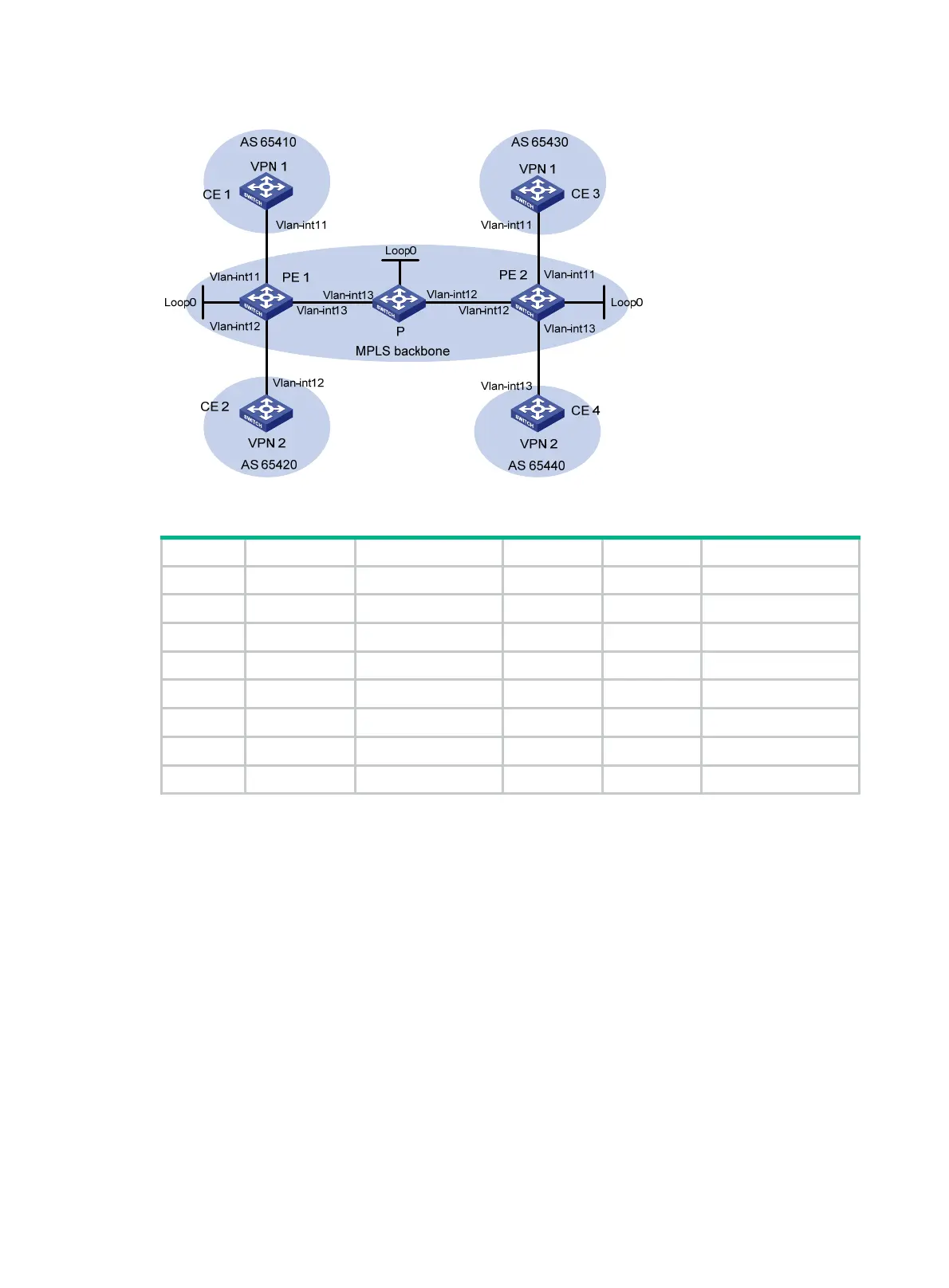
Figure 83 Network diagram
Table 27 Interface and IP address assignment
Device Interface IP address Device Interface IP address
CE 1 Vlan-int11 2001:1::1/96 P Loop0 2.2.2.9/32
PE 1 Loop0 1.1.1.9/32 Vlan-int12 172.2.1.1/24
Vlan-int11 2001:1::2/96 Vlan-int13 172.1.1.2/24
Vlan-int13 172.1.1.1/24 PE 2 Loop0 3.3.3.9/32
Vlan-int12 2001:2::2/96 Vlan-int12 172.2.1.2/24
CE 2 Vlan-int12 2001:2::1/96 Vlan-int11 2001:3::2/96
CE 3 Vlan-int11 2001:3::1/96 Vlan-int13 2001:4::2/96
CE 4 Vlan-int13 2001:4::1/96
532BConfiguration procedure
1. Configure OSPF on the MPLS backbone to ensure IP connectivity among the PEs and the P
switch:
# Configure PE 1.
<PE1> system-view
[PE1] interface loopback 0
[PE1-LoopBack0] ip address 1.1.1.9 32
[PE1-LoopBack0] quit
[PE1] interface vlan-interface 13
[PE1-Vlan-interface13] ip address 172.1.1.1 24
[PE1- Vlan-interface13] quit
[PE1] ospf
[PE1-ospf-1] area 0
[PE1-ospf-1-area-0.0.0.0] network 172.1.1.0 0.0.0.255
[PE1-ospf-1-area-0.0.0.0] network 1.1.1.9 0.0.0.0
[PE1-ospf-1-area-0.0.0.0] quit

 Loading...


