323
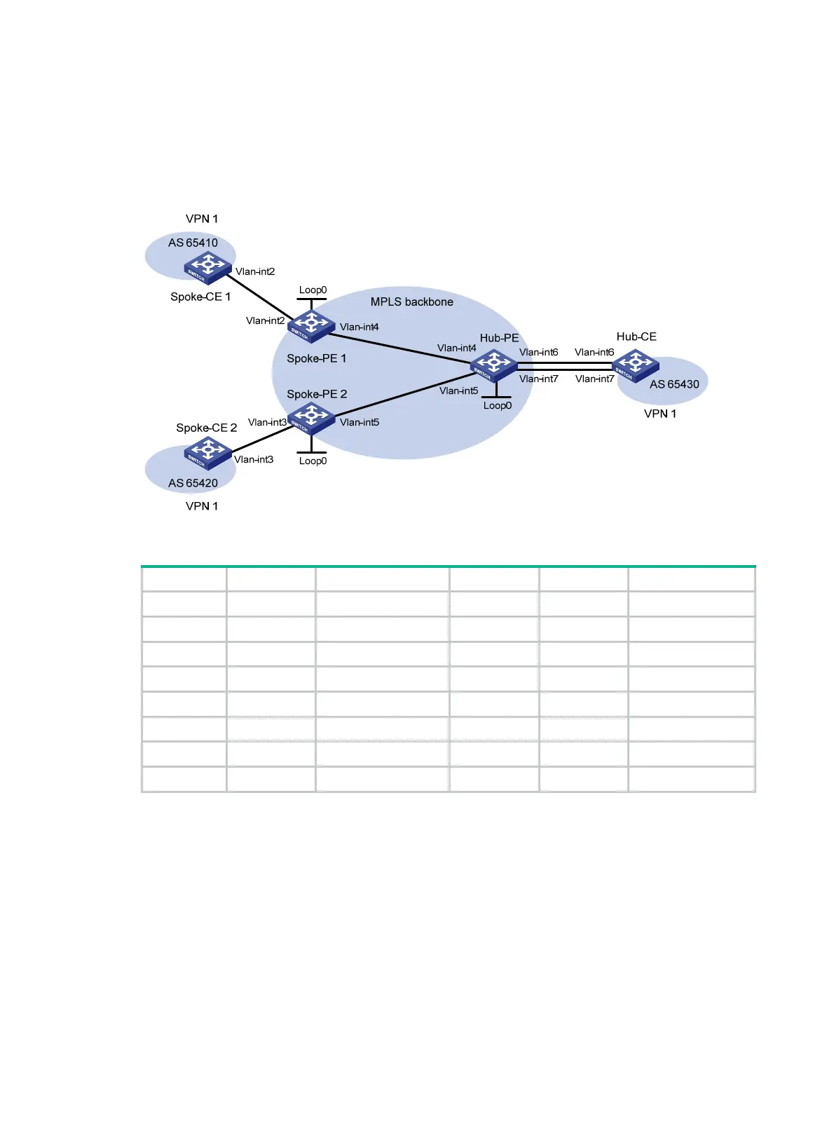
Configure EBGP between the Spoke-CEs and Spoke-PEs and between the Hub-CE and Hub-PE to
exchange VPN routing information.
Configure OSPF between the Spoke-PEs and Hub-PE to implement communication between the
PEs. Configure MP-IBGP between the Spoke-PEs and Hub-PE to exchange VPN routing
information.
Figure 84 Network diagram
Table 28 Interface and IP address assignment
Device Interface IP address Device Interface IP address
Spoke-CE 1 Vlan-int2 11::1/64 Hub-CE Vlan-int6 13::1/64
Spoke-PE 1 Loop0 1.1.1.9/32 Vlan-int7 14::1/64
Vlan-int2 11::2/64 Hub-PE Loop0 2.2.2.9/32
Vlan-int4 172.1.1.1/24 Vlan-int4 172.1.1.2/24
Spoke-CE 2 Vlan-int3 12::1/64 Vlan-int5 172.2.1.2/24
Spoke-PE 2 Loop0 3.3.3.9/32 Vlan-int6 13::2/64
Vlan-int3 12::2/64 Vlan-int7 14::2/64
Vlan-int5 172.2.1.1/24
535BConfiguration procedure
1. Configure an IGP on the MPLS backbone to ensure IP connectivity within the backbone:
# Configure Spoke-PE 1.
<Spoke-PE1> system-view
[Spoke-PE1] interface loopback 0
[Spoke-PE1-LoopBack0] ip address 1.1.1.9 32
[Spoke-PE1-LoopBack0] quit
[Spoke-PE1] interface vlan-interface 4
[Spoke-PE1-Vlan-interface4] ip address 172.1.1.1 24
[Spoke-PE1-Vlan-interface4] quit
[Spoke-PE1] ospf

 Loading...


