386
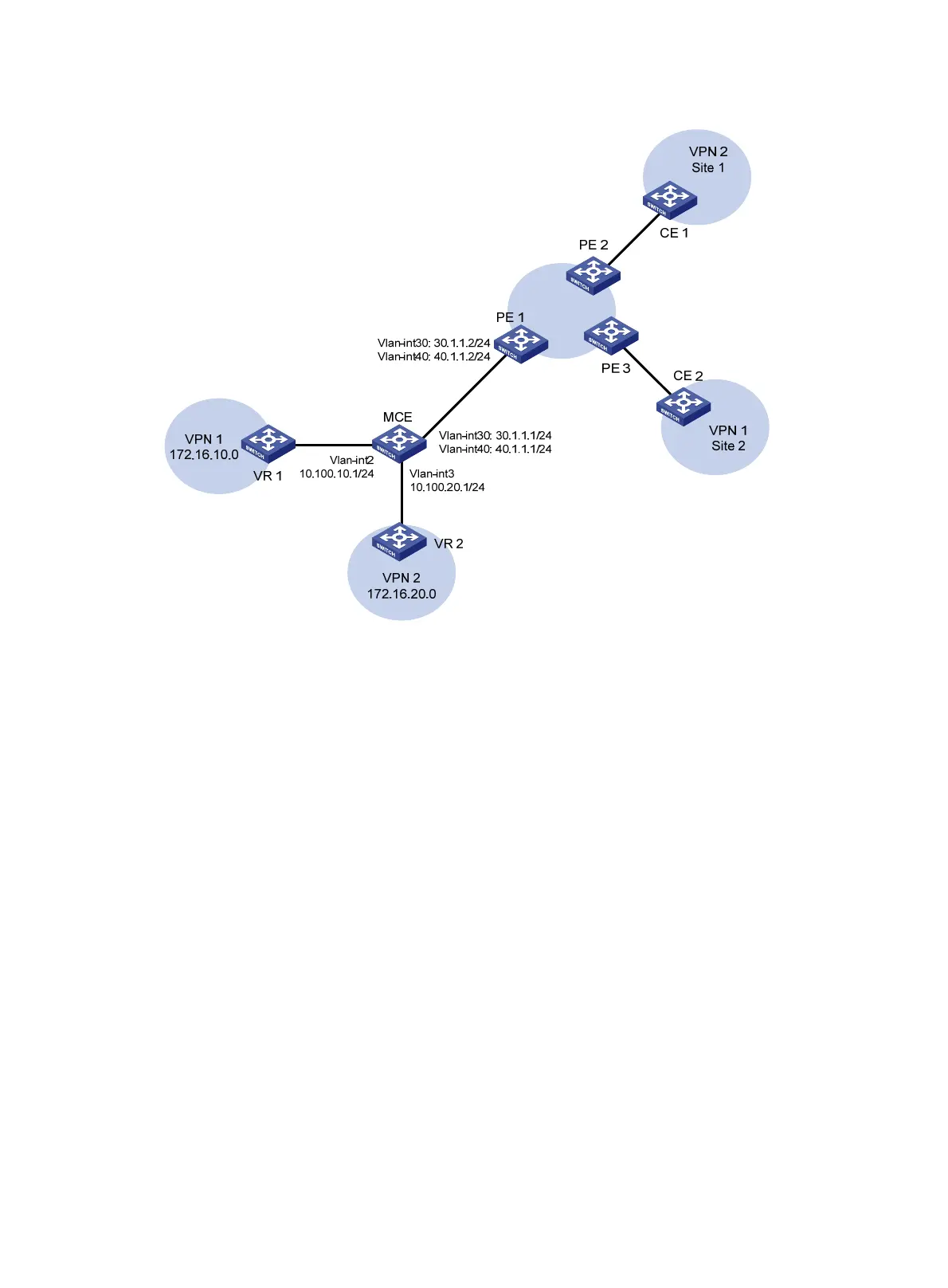
Figure 96 Network diagram
575BConfiguration procedure
1. Create VPN instances on the MCE and PE 1, and bind the VPN instances to VLAN interfaces.
For the configuration procedure, see "
869HConfiguring the MCE that uses OSPF to advertise VPN
routes to the PE."
2. Configure routing between the MCE and VPN sites:
# Enable an OSPF process on the devices in the two VPNs, and advertise the subnets. (Details
not shown.)
# Configure OSPF on the MCE, and bind OSPF process 10 to VPN instance vpn1 to learn the
routes of VPN 1.
<MCE> system-view
[MCE] ospf 10 router-id 10.10.10.1 vpn-instance vpn1
[MCE-ospf-10] area 0
[MCE-ospf-10-area-0.0.0.0] network 10.214.10.0 0.0.0.255
[MCE-ospf-10-area-0.0.0.0] quit
[MCE-ospf-10] quit
# Display the routing table of VPN 1 on the MCE.
[MCE] display ip routing-table vpn-instance vpn1
Destinations : 13 Routes : 13
Destination/Mask Proto Pre Cost NextHop Interface
0.0.0.0/32 Direct 0 0 127.0.0.1 InLoop0
10.214.10.0/24 Direct 0 0 10.214.10.3 Vlan10
10.214.10.0/32 Direct 0 0 10.214.10.3 Vlan10

 Loading...


