HSD
5801H0056 ______________________________________________________________ 112/181
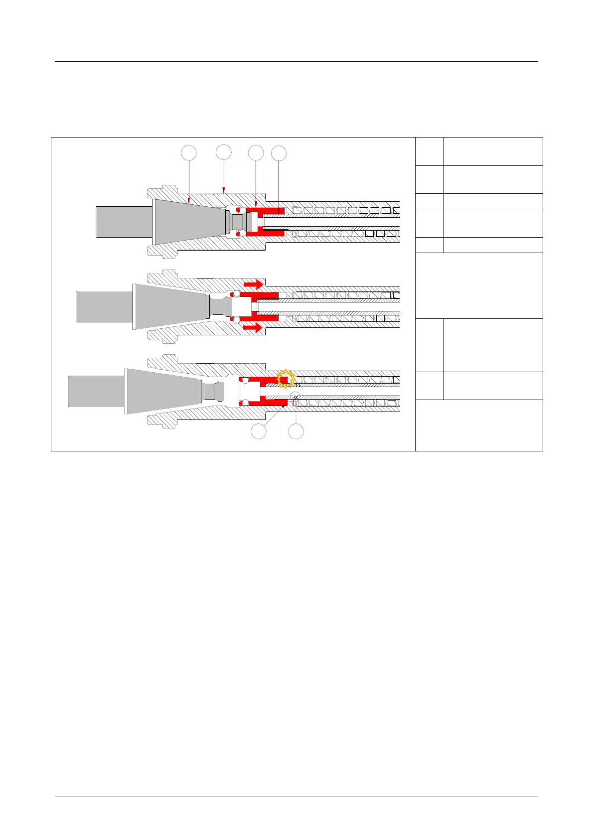
If these procedures are not observed, the tool-holder will drag the locking system (collet/tie-rod)
with it until the collet spindle is freed; owing to the force of the spring, the collet will then shoot back
violently, perhaps breaking the tie-rod
N
.
Description
1
ISO collet
spindle
2
Spindle shaft
3
ISO collet
(or bush)
4
Tie-rod
The arrows show the
direction in which the
blocking system
moves after freeing
the collet spindle
5
Point in which
the collet
knocks against
the shaft
6
Breakage of the
tie-rod
UTENSILE BLOCCATO
IMPATTO
1
2
3
4
UTENSILE RILASCIATO
5
6