HSD
5801H0056 ______________________________________________________________ 161/181
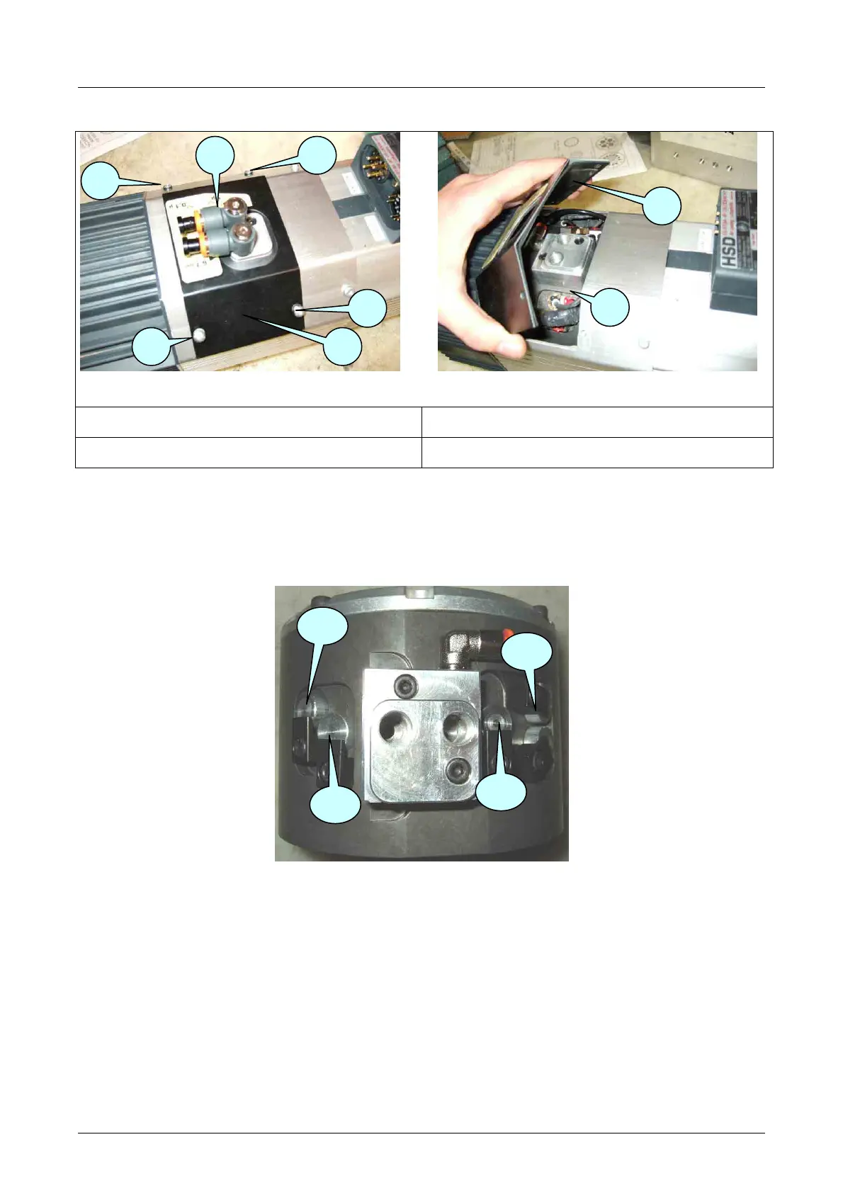
8.8.6 Accessing the sensors
Figure8 6.
Figure 8.7
1
Pair of quick connectors
3
Sensor area cover
2
Screws
4
Sensor area
• Disconnect the quick connectors 1 from the tubes and rotate them towards the spindle nose.
• Loosen the screws 2 to free the cover 3.
• Lift up the cover 3 to access the area 4, being careful not to damage the interposed gasket.
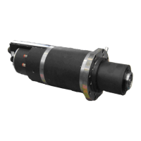
8.8.7 Position of the sensors
Figure 8.8 identification of the sensors
3
4
1
2
3
2
2
2
S4
S1
S3
S2